LM2796TLEV National Semiconductor, LM2796TLEV Datasheet - Page 6
LM2796TLEV
Manufacturer Part Number
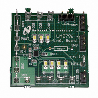
LM2796TLEV
Description
BOARD EVALUATION LM2796TL
Manufacturer
National Semiconductor
Series
PowerWise®r
Specifications of LM2796TLEV
Current - Output / Channel
20mA
Outputs And Type
7, Non-Isolated
Voltage - Output
4 V
Features
Charge Pump
Voltage - Input
2.7 ~ 5.5V
Utilized Ic / Part
LM2796
Lead Free Status / RoHS Status
Not applicable / Not applicable


www.national.com
Circuit Description
OVERVIEW
The LM2796 is primarily intended for Lithium-Ion battery
driven white-LED drive applications, and is well suited to
drive white LEDs that are used for backlighting small-format
displays. The part has seven matched constant-current out-
puts, each capable of driving up to 20mA (or more) through
white LEDs. The well-matched current sources ensure the
current through all the LEDs is virtually identical. This keeps
brightness of all LEDs matched to near perfection so that
they can provide a consistent backlight over the entire dis-
play.
The core of the LM2796 is a 1.5x/1x dual-mode charge
pump. The input of the charge pump is connected to the V
pin. The recommended input voltage range of the LM2796 is
2.7V to 5.5V. The output of the charge pump is the P
( “Pump OUTput”). The output voltage of the charge pump is
unregulated and varies with input voltage and load current.
The charge pump operates in the 1.5x mode when the input
voltage is below 4.75V (typ.). In this mode, the input-to-
output voltage gain of the charge pump is 1.5, and the
voltage at the output of the charge pump will be approxi-
mately 1.5x the input voltage (V(P
the 1.5x mode, the charge pump provides the voltage boost
that is required to drive white LEDs from a Li-Ion battery.
(White LEDs typically have a forward voltage in the range of
3.3V to 4.0V. A Li-Ion battery typically is not considered to be
fully discharged until the battery voltage falls to 3.0V (ap-
prox.) )
The charge pump operates in the 1x mode when the input
voltage is above 4.75V (typ.). In these conditions, voltage
boost is not required to drive the LEDs, so the charge pump
merely passes the input voltage to P
This reduces the input current and the power dissipation of
the LM2796 when the input voltage is high.
The matched current outputs are generated with a precision
current mirror that is biased off the charge pump output.
Matched currents are ensured with the use of tightly
matched internal devices and internal mismatch cancellation
circuitry. Top-side current drive allows LEDs to be connected
between each current output and GND, simplifying PWB
routing and connectivity.
There are seven regulated current outputs. These seven
outputs are split into two groups, a group of 4 outputs and a
group of 3 outputs. There is an ON/OFF control pin for each
group.
The DC current through the LEDs is programmed with an
external resistor. Changing currents on-the-fly can be
achieved with the use of digital pulse (PWM) signals.
ENABLE PINS: EN, ENA, ENB
The LM2796 has 3 enable pins. All three are active-high
logic (HIGH = ON). There are internal pull-down resistors
(300kΩ typ.) that are connected internally between each of
the enable pins and GND.
The EN pin is the master enable pin for the part. When
voltage on this pin is low (
mode. All internal circuitry is OFF and the part consumes
very little supply current when the LM2796 is shutdown.
When the voltage on the EN pin is high (
active. The charge pump is ON, and it is possible to turn on
the output currents to drive the LEDs.
<
0.5V), the part is in shutdown
OUT
) ≈ 1.5 * V
OUT
>
(V(P
1.1V), the part is
IN
OUT
). When in
) ≈ V
OUT
IN
pin
IN
).
6
ENA and ENB are used to turn the output currents ON and
OFF. ENA activates/deactivates the four group-A outputs
(D1A-D4A). ENB activates/deactivates the three group-B
outputs (D1B-D3B).
SETTING LED CURRENTS
The output currents of the LM2796 can be set to a desired
value simply by connecting an appropriately sized resistor
(R
output currents (LED currents) are proportional to the current
that flows out of the I
of 100 greater than the I
internal amplifier sets the voltage of the I
(typ.). Placing a resistor between I
the I
above are simplified in the equations below:
Maximum Output Current, Maximum LED Voltage,
Minimum Input Voltage
The LM2796 can drive 7 LEDs at 15mA each from an input
voltage as low as 3.0V, so long as the LEDs have a forward
voltage of 3.6V or less (room temperature).
The statement above is a simple example of the LED drive
capabilities of the LM2796. The statement contains the key
application parameters that are required to validate an LED-
drive design using the LM2796: LED current (I
of active LEDs (N), LED forward voltage (V
mum input voltage (V
The equation below can be used to estimate the total output
current capability of the LM2796:
R
nal losses of the charge pump that result in voltage droop at
the pump output P
droop is proportional to the total output current of the charge
pump, the loss parameter is modeled as a resistance. The
output resistance of the LM2796 is typically 2.7Ω (V
T
k
mum voltage required to be present across the current
sources for them to regulate properly. This minimum voltage
is proportional to the programmed LED current, so the con-
stant has units of mV/mA. The typical k
22mV/mA. In equation form:
The "I
the R
solving for I
on minimum input voltage and LED forward voltage. Output
current capability can be increased by raising the minimum
input voltage of the application, or by selecting an LED with
a lower forward voltage. Excessive power dissipation may
also limit output current capability of an application.
Soft Start
The LM2796 contains internal soft-start circuitry to limit input
inrush currents when the part is enabled. Soft start is imple-
mented internally with a controlled turn-on of the internal
voltage reference. During soft start, the current through the
I
I
LED_MAX
HR
LED_MAX
A
OUT
SET
= 25˚C). In equation form:
SET
– Headroom constant. This parameter models the mini-
OUT
) between the I
– Output resistance. This parameter models the inter-
LED-MAX
V
current, and thus the LED currents. The statements
POUT
= ((1.5 x V
equation (eq. 2) with the k
= ((1.5 x V
(V
LED
POUT
" equation (eq. 1) is obtained from combining
= 1.5xV
. Maximum LED current is highly dependent
R
I
Dxx
SET
– V
OUT
SET
IN
IN
SET
= 100 x(V
IN-MIN
= 100 x (1.25V / I
LED
) - V
. Since the magnitude of the voltage
IN
) - V
SET
pin. The output currents are a factor
– NxI
)
pin of the LM2796 and GND. The
LED
>
).
current. The feedback loop of an
LED
k
) / ((N x R
HR
LED
SET
) / ((N x 2.7Ω) + 22mV/mA)
xI
xR
LED
SET
/ R
HR
OUT
SET
equation (eq. 3) and
HR
and GND programs
Dxx
OUT
)
SET
)
of the LM2796 is
(eq. 3)
) + k
LED
(eq. 2)
LED
pin to 1.25V
), and mini-
HR
), number
IN
) (eq. 1)
= 3.0V,
Related parts for LM2796TLEV
Image
Part Number
Description
Manufacturer
Datasheet
Request
R

Part Number:
Description:
Accurate, 120 C-150 C Factory Preset Thermostat Lm27 Form
Manufacturer:
National Semiconductor Corporation
Datasheet:

Part Number:
Description:
Factory Preset Thermostat
Manufacturer:
National Semiconductor
Datasheet:
Part Number:
Description:
National Semiconductor [8-Bit D/A Converter]
Manufacturer:
National Semiconductor
Datasheet:
Part Number:
Description:
National Semiconductor [Media Coprocessor]
Manufacturer:
National Semiconductor
Datasheet:
Part Number:
Description:
Digitally Controlled Tone and Volume Circuit with Stereo Audio Power Amplifier, Microphone Preamp Stage and National 3D Sound
Manufacturer:
National Semiconductor
Datasheet:
Part Number:
Description:
Digitally Controlled Tone and Volume Circuit with Stereo Audio Power Amplifier, Microphone Preamp Stage and National 3D Sound
Manufacturer:
National Semiconductor
Datasheet:
Part Number:
Description:
AC97 Rev 2 Codec with Sample Rate Conversion and National 3D Sound
Manufacturer:
National Semiconductor
Part Number:
Description:
Manufacturer:
National Semiconductor
Datasheet:
Part Number:
Description:
Manufacturer:
National Semiconductor
Datasheet:
Part Number:
Description:
General Purpose, Low Voltage, Low Power, Rail-to-Rail Output Operational Amplifiers
Manufacturer:
National Semiconductor
Datasheet:
Part Number:
Description:
8-bit 20 MSPS flash A/D converter.
Manufacturer:
National Semiconductor
Datasheet:
Part Number:
Description:
Low Noise Quad Operational Amplifier
Manufacturer:
National Semiconductor
Datasheet:
Part Number:
Description:
Quad Differential Line Receivers
Manufacturer:
National Semiconductor
Datasheet:
Part Number:
Description:
Quad High Speed Trapezoidal? Bus Transceiver
Manufacturer:
National Semiconductor
Datasheet: