LM3404MREVAL National Semiconductor, LM3404MREVAL Datasheet - Page 2
LM3404MREVAL
Manufacturer Part Number
LM3404MREVAL
Description
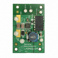
BOARD EVALUATION LM3404MR
Manufacturer
National Semiconductor
Series
PowerWise®r
Specifications of LM3404MREVAL
Current - Output / Channel
1A
Outputs And Type
1, Non-Isolated
Voltage - Output
37V
Features
Dimmable
Voltage - Input
6 ~ 42 V
Utilized Ic / Part
LM3404
Lead Free Status / RoHS Status
Contains lead / RoHS non-compliant


www.national.com
Calibrated testing was performed on the PSOP-8 evaluation
board to compare the performance of the PSOP-8 with the
DAP soldered and the standard SO-8 package. The example
circuit
LM3404/04HV datasheet for detailed thermal calculations.)
For dissipation ranging from 0.5W to 1.5W the θ
PSOP-8 package is 50°C/W ±10%. The θ
age is 100°C/W ±10%.
Connecting to LED Array
The LM3404/04HV Evaluation Board includes a female 6-pin
SIP, J1, connector as well as two standard 94mil turret con-
nectors for the cathode and anode connections of the LED
array. Figure 3 shows the pinout of J1. Solid 18 or 20 gauge
wire with about 1 cm of insulation stripped away makes a
convenient, solderless connection to J1.
Setting the LED Current
The default forward current I
1.0A, typical of many 3W LEDs. To adjust this value the cur-
dissipation
FIGURE 3. LED Connector
is
approximately
F
delivered to the LED array is
JA
1.1W.
of the SO-8 pack-
30009201
FIGURE 4. PWM Dimming Limits
(see
JA
of the
the
2
rent setting resistor R
following equation:
This resistor should be rated to handle the power dissipation
of the LED current. For this example, the closest 5% tolerance
resistor to set an LED current of 1.0A is 0.2 Ω. In steady state
this resistor will dissipate (1.0 x 0.2) = 200 mW, indicating that
a resistor with a 1/4W power rating is appropriate.
PWM Dimming
The DIM terminal on the PCB provides an input for a pulse
width modulation signal for dimming of the LED array. In order
to fully enable and disable the LM3404/04HV the PWM signal
should have a maximum logic low level of 0.8V and a mini-
mum logic high level of 2.2V. The maximum PWM dimming
frequency, minimum PWM duty cycle and maximum duty cy-
cle are illustrated in Figure 4. PWM frequency should be at
least one order of magnitude below the LM3404/04HV switch-
ing frequency. The interval t
logic high at the DIM pin to the onset of the output current.
The quantities t
output current to slew up to steady state and slew down to
zero, respectively. Typical response time is shown in the Typ-
ical Performance Characteristics section.
SU
and t
SNS
t
SD
SNS
can be changed according to the
represent the time needed for the
= 220 ns
D
represents the delay from a
30009202
Related parts for LM3404MREVAL
Image
Part Number
Description
Manufacturer
Datasheet
Request
R

Part Number:
Description:
IC LED DRVR HP CONST CURR 8-PSOP
Manufacturer:
National Semiconductor
Datasheet:

Part Number:
Description:
IC,Laser Diode/LED Driver,SOP,8PIN,PLASTIC
Manufacturer:
National Semiconductor

Part Number:
Description:
THREE TERMINAL POSITIVE FIXED VOLTAGE REGULATORS
Manufacturer:
Motorola Inc
Datasheet:
Part Number:
Description:
Manufacturer:
National Semiconductor Corporation
Datasheet:
Part Number:
Description:
National Semiconductor [8-Bit D/A Converter]
Manufacturer:
National Semiconductor
Datasheet:
Part Number:
Description:
National Semiconductor [Media Coprocessor]
Manufacturer:
National Semiconductor
Datasheet:
Part Number:
Description:
Digitally Controlled Tone and Volume Circuit with Stereo Audio Power Amplifier, Microphone Preamp Stage and National 3D Sound
Manufacturer:
National Semiconductor
Datasheet:
Part Number:
Description:
Digitally Controlled Tone and Volume Circuit with Stereo Audio Power Amplifier, Microphone Preamp Stage and National 3D Sound
Manufacturer:
National Semiconductor
Datasheet:
Part Number:
Description:
AC97 Rev 2 Codec with Sample Rate Conversion and National 3D Sound
Manufacturer:
National Semiconductor