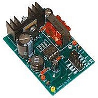
IRPLLED1 International Rectifier, IRPLLED1 Datasheet - Page 4

IRPLLED1
Manufacturer Part Number
IRPLLED1
Description
BOARD EVALUATION FOR IRS2540PBF
Manufacturer
International Rectifier
Specifications of IRPLLED1
Current - Output / Channel
1.5A
Outputs And Type
1, Non-Isolated
Voltage - Output
24V
Features
Dimmable
Voltage - Input
50 ~ 170V
Utilized Ic / Part
IRS2540PBF
Core Chip
IRS2540, IRS2541, IRS25401
Topology
Buck (Step Down)
No. Of Outputs
1
Output Current
1.5A
Output Voltage
500mV
Dimming Control Type
PWM
Development Tool Type
Hardware - Eval/Demo Board
Lead Free Status / RoHS Status
Contains lead / RoHS compliant by exemption
www.irf.com
Electrical Characteristics
V
CC
= V
Symbol
Supply Characteristics
Floating Supply Characteristics
Current Control Operation
Gate Driver Output Characteristics
V
I
V
V
V
V
V
V
t
I
V
V
t
BS
QCCENN
t
I
t
HO,OFF
QCCUV
I
I
LO,OFF
ENNTH+
HO,ON
I
CC50k
ENNTH-
LO,ON
CCUV+
UVHYS
CLAMP
V
V
V
I
CCUV-
QBS0
QBS1
BSUV+
DT
BSUV-
IFBTH
QCC
I
O+/-
LK
t
t
f
= V
0.5
OL
HL
r
f
BIAS
V
threshold
V
threshold
V
UVLO mode quiescent current
Diesabled mode quiescent current
Quiescent V
V
V
Quiescent V
Quiescent V
V
threshold
V
threshold
Offset supply leakage current
ENN pin positive threshold
ENN pin negative threshold
0.5 V voltage reference (die level test)
IFB pin threshold
Maximum frequency
Low level output voltage (HO or LO)
High level output voltage (HO or LO)
Turn-on rise time
Turn-off fall time
Output source/sink short circuit pulsed current
Deadtime
Delay between V
Delay between V
Delay between V
Delay between V
= 14 V +/- 0.25 V, C
CC
CC
CC
CC
CC
BS
BS
supply undervoltage positive going
supply undervoltage negative going
supply undervoltage positive going
supply undervoltage negative going
supply undervoltage lockout hysteresis
supply current, f = 50 kHz
zener clamp voltage
CC
BS
BS
supply current
supply current
supply current
IFB
IFB
IFB
IFB
Definition
>V
<V
<V
>V
LO
=C
IFBTH
IFBTH
IFBTH
IFBTH
HO
and LO turn-on
and LO turn-off
and HO turn-on
and HO turn-off
=1000 pF, C
VCC
=C
VBS
=0.1 μF, T
Min
14.6
490
455
8.0
6.5
1.0
6.5
6.0
2.5
1.7
---
---
---
---
---
---
---
---
---
---
---
---
---
---
---
---
---
---
0.5/0.7
A
COM
Typ Max
15.6
=25 °C unless otherwise specified.
500
500
500
140
320
180
320
180
V
9.0
7.5
1.2
1.0
1.0
2.0
1.0
2.0
7.5
7.0
2.7
2.0
50
50
30
1
CC
10.0
16.6
150
510
540
120
8.5
2.0
2.0
2.0
3.0
2.0
3.0
8.5
8.0
3.0
2.3
50
---
---
---
50
---
---
---
---
---
---
Units Test Conditions
kHz
mA
mA
mV
µA
µA
ns
ns
V
V
V
V
V
A
IRS254(0,1)(S)PbF
IRS2540:V
IRS2541:V
V
wave, 200 mV pk-pk
DC offset = 400 mV
I
V
FB
Duty Cycle = 50%
Duty Cycle = 50%
CC
CC
= 50 kHz square
falling from 14 V
I
rising from 0 V
EN>V
CC
f = 50 kHz
V
I
I
V
FB
FB
HO
CC
= 10 mA
= 1 V
= 0 V
=6 V
B
B
= V
=V
=V
ENTH+
S
S
S
=200 V
=600 V
Page 4


