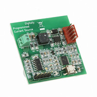
MCP1631RD-DCPC1 Microchip Technology, MCP1631RD-DCPC1 Datasheet - Page 15

MCP1631RD-DCPC1
Manufacturer Part Number
MCP1631RD-DCPC1
Description
REF DES BATT CHARG OR LED DRIVER
Manufacturer
Microchip Technology
Datasheets
1.PIC16F616T-ISL.pdf
(214 pages)
2.MCP1631VHVT-330EST.pdf
(34 pages)
3.MCP1631VHVT-330EST.pdf
(32 pages)
Specifications of MCP1631RD-DCPC1
Current - Output / Channel
700mA
Outputs And Type
1, Non-Isolated
Features
Firmware for Li-Ion, NiMH, and NiCd Battery Charger
Voltage - Input
3.5 ~ 16 V
Utilized Ic / Part
MCP1631HV, PIC16F616
Core Chip
MCP1631HV, PIC16F616
Topology
Parallel, Series
Output Current
1A
No. Of Outputs
1
Input Voltage
3.5V To 16V
Dimming Control Type
Analog
Kit Contents
Board
Lead Free Status / RoHS Status
Lead free / RoHS Compliant
Voltage - Output
-
Lead Free Status / Rohs Status
Lead free / RoHS Compliant
© 2009 Microchip Technology Inc.
2.3.1
2.3.1.1
1. Prepare the power supply to be connected to the input terminal block, J1. The
2. Connect the positive side of the input source (+) to pin +V
FIGURE 2-4:
2.3.1.2
1. To apply an LED load to the MCP1631HV Digitally Controlled Programmable
2. Optionally, a thermistor referenced to the (-) pin of J2 may be utilized for thermal
+V
GND
Note:
input voltage source should be limited to the 0V to +16V range. For nominal
operations, the recommended input voltage should be between +3.5 and +16
volts with a 12W input supply.
negative or return side (-) of the input source to pin GND of J1. Refer to
Figure 2-4.
Current Source Reference Design, the anode of the LED should be connected
to pin 1 (+) of J2. The cathode of the LED should be connected to pin 5 (-) of J2.
The default drive current for LEDs is set to 700 mA in the supplied firmware. The
LED load which is connected to the reference board must be capable of handling
700 mA. If the LED load is not capable of handling 700 mA, then the firmware
must be re-compiled with the LED drive current set to the current capability of the
LED load being used. The minimum programmed current that the board will
generate is 10% of the programmed drive current. For the reference board
firmware which is set to 700 mA of drive current, the minimum would be 70 mA.
shutdown.
The recommended thermistor is EPCOS Inc. P/N: B57500M0103A005.
IN
Power Input and Output Connection
POWERING THE MCP1631HV DIGITALLY PROGRAMMABLE
CURRENT SOURCE REFERENCE DESIGN
APPLYING A LOAD TO THE MCP1631HV DIGITALLY CONTROLLED
PROGRAMMABLE CURRENT SOURCE REFERENCE DESIGN
The Thermal Shutdown is not enabled by default in the firmware. It can be
enabled by re-compiling the source code with this feature enabled. The
thermistor must be used if the board is programmed with NiMH/NiCd
charger firmware.
Power Supply and Load Connections Diagram.
Installation and Operation
IN
(+) THERMISTOR (optional)
(-) LED Cathode
(-) THERMISTOR (optional)
(+) LED Anode
of J1. Connect the
DS51798A-page 11


