MCP1252DM-BKLT Microchip Technology, MCP1252DM-BKLT Datasheet - Page 13
MCP1252DM-BKLT
Manufacturer Part Number
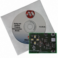
MCP1252DM-BKLT
Description
BOARD DEMO FOR MCP1252
Manufacturer
Microchip Technology
Specifications of MCP1252DM-BKLT
Current - Output / Channel
120mA
Outputs And Type
1, Non-Isolated
Features
Short-Circuit and Thermal Protection, Shutdown
Voltage - Input
2 ~ 5.5V
Utilized Ic / Part
MCP1252
Processor To Be Evaluated
MCP1252
Lead Free Status / RoHS Status
Contains lead / RoHS non-compliant
Voltage - Output
-
Lead Free Status / Rohs Status
Lead free / RoHS Compliant


© 2005 Microchip Technology Inc.
Activating Application and Changing the LED intensity
1. To activate the LEDs, simply press the S1 push button. The LEDs will turn on at
2. The LEDs will be turned off, and the system will enter Sleep mode, when the
Evaluating the Application
The best way to evaluate the MCP1252 Charge Pump Backlight LED Demo Board is
to dig into the circuit. Measure voltages and currents with a DVM and probe the board
with an oscilloscope. Test points have been provided to simplify this task. The test
points correspond to the pins of the MCP1252: PGD (= PGOOD), Vout, V
GND, SHDN and FB.
The firmware program in the PIC10F206 can also be edited to modify the operation of
the application. For example, the output signal that is routed from GP0 of the
PIC10F206 to SHDN of the MCP1252 can be changed to implement different light
intensities, slowly blinking the LEDs on/off or provide some other pattern. There is also
an optional push button (S2) that can be used to provide additional control options to
the system
Firmware
The PIC10F206 comes preprogrammed with firmware to operate the system as
described above. The program file can be found on the CD that comes with the kit. The
file listing and firmware flow diagram are shown in Appendix C. “00016R1.asm
Source Code”.
The program is fairly simple and straightforward. There is an initialization routine at the
beginning of the program. The constants allow for five LED intensity levels to be
adjusted to the appropriate light intensity (LED_HI_ON, LED_MEDHI_ON, etc.), set the
PWM period (PERIOD) and maximum time (MAX_TIME) before the unit switches back
to Sleep mode. The variables track what mode the unit is in (MODE), implement
counters (COUNTER, TIMERH, TIMERL), etc.
Upon resetting the processor, the ports are initialized and registers are configured in
the INIT_PORTS routine. If the device has come out of Sleep mode, the MODE variable
is set so the LEDs will be at low intensity. The OPTION register is configured to
wake-up on Port pin change. The GPIO port is configured to set GP0 (PWM to the
MCP1252) as an output and GP1, GP2 and GP3 (push button) as inputs. The
processor will reset on power-up or due to a wake-up from Sleep mode. Therefore, the
STATUS register needs to be tested to determine the source of the reset. If the reset
occurred due to powering up the system for the first time, the program proceeds to the
INIT_VARS subroutine, where the program variables are initialized. If the reset
occurred due to a wake-up from Sleep mode, the program proceeds to the WAKE
subroutine.
The intensity of the LEDs are controlled via the SHDN input pin of the MCP1252.
A Pulse-Width Modulated (PWM) signal is generated by the PIC10F206 and routed
to the SHDN input pin of the MCP1252. The MCP1252 is actually pulsed, and the
duty cycle of the PWM waveform is varied, such that narrow pulses create a
low-intensity condition, while wider pulses create a high-intensity condition.
a low intensity level when the push button is pressed, gaining intensity when the
push button is pressed again. There are 5 levels of LED intensity (plus the “off”
state).
LEDs are in the high-intensity state and the push button is pressed. Subsequent
push button presses will cycle the LEDs as described in Step 1.
Installation and Operation
DS51551A-page 9
DD
(= V
IN
),
Related parts for MCP1252DM-BKLT
Image
Part Number
Description
Manufacturer
Datasheet
Request
R

Part Number:
Description:
Manufacturer:
Microchip Technology Inc.
Datasheet:
Part Number:
Description:
Manufacturer:
Microchip Technology Inc.
Datasheet:
Part Number:
Description:
Manufacturer:
Microchip Technology Inc.
Datasheet:
Part Number:
Description:
Manufacturer:
Microchip Technology Inc.
Datasheet:
Part Number:
Description:
Manufacturer:
Microchip Technology Inc.
Datasheet:
Part Number:
Description:
Manufacturer:
Microchip Technology Inc.
Datasheet:
Part Number:
Description:
Manufacturer:
Microchip Technology Inc.
Datasheet:
Part Number:
Description:
Manufacturer:
Microchip Technology Inc.
Datasheet: