LM3445-208277EV/NOPB National Semiconductor, LM3445-208277EV/NOPB Datasheet - Page 10
LM3445-208277EV/NOPB
Manufacturer Part Number
LM3445-208277EV/NOPB
Description
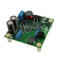
BOARD EVAL LED DRIVER LM3445
Manufacturer
National Semiconductor
Series
PowerWise®r
Specifications of LM3445-208277EV/NOPB
Current - Output / Channel
500mA
Outputs And Type
1, Non-Isolated
Features
Dimmable with Standard TRIAC Dimmer, Power Factor Correction
Voltage - Input
176 ~ 305 VAC
Utilized Ic / Part
LM3445
Lead Free Status / RoHS Status
Lead free / RoHS Compliant
Voltage - Output
-
Other names
LM3445-208277EV
Available stocks
Company
Part Number
Manufacturer
Quantity
Price
Company:

Part Number:
LM3445-208277EV/NOPB
Manufacturer:
National Semiconductor
Quantity:
135


www.national.com
SENSING THE RECTIFIED TRIAC WAVEFORM
A bridge rectifier, BR1, converts the line (mains) voltage (5c)
into a series of half-sines as shown in 5b. Figure 5a shows a
typical voltage waveform after diode D3 (valley fill circuit, or
V
Figure 6c and 6b show typical triac dimmed voltage wave-
forms before and after the bridge rectifier. Figure 6a shows a
typical triac dimmed voltage waveform after diode D3 (valley
fill circuit, or V
FIGURE 6. Voltage Waveforms After Bridge Rectifier With
LM3445 LINE SENSING CIRCUITRY
An external series pass regulator (R2, D1, and Q1) translates
the rectified line voltage to a level where it can be sensed by
the BLDR pin on the LM3445.
BUCK
FIGURE 5. Voltage Waveforms After Bridge Rectifier
).
BUCK
Without Triac Dimming
).
Triac Dimming
30060316
30060315
10
D1 is typically a 15V zener diode which forces transistor Q1
to “stand-off” most of the rectified line voltage. Having no ca-
pacitance on the source of Q1 allows the voltage on the BLDR
pin to rise and fall with the rectified line voltage as the line
voltage drops below zener voltage D1 (see the section on
Angle Detect).
A diode-capacitor network (D2, C5) is used to maintain the
voltage on the VCC pin while the voltage on the BLDR pin
goes low. This provides the supply voltage to operate the
LM3445.
Resistor R5 is used to bleed charge out of any stray capaci-
tance on the BLDR node and may be used to provide the
necessary holding current for the dimmer when operating at
light output currents.
TRIAC HOLDING CURRENT RESISTOR
In order to emulate an incandescent light bulb (essentially a
resistor) with any LED driver, the existing triac will require a
small amount of holding current throughout the AC line cycle.
An external resistor (R5) needs to be placed on the source of
Q1 to GND to perform this function. Most existing triac dim-
mers only require a few milliamps of current to hold them on.
A few “less expensive” triacs sold on the market will require
a bit more current. The value of resistor R5 will depend on:
•
•
With a single LM3445 circuit on a common triac dimmer, a
holding current resistor between 3 kΩ and 5 kΩ will be re-
quired. As the number of LM3445 circuits is added to a single
dimmer, the holding resistor R5’s resistance can be in-
creased. A few triac dimmers will require a resistor as low as
1 kΩ or lower for a single LM3445 circuit. The trade-off will be
What type of triac the LM3445 will be used with
How many light fixtures are running off of the triac
FIGURE 7. LM3445 AC Line Sense Circuitry
30060317
Related parts for LM3445-208277EV/NOPB
Image
Part Number
Description
Manufacturer
Datasheet
Request
R

Part Number:
Description:
National Semiconductor [8-Bit D/A Converter]
Manufacturer:
National Semiconductor
Datasheet:
Part Number:
Description:
National Semiconductor [Media Coprocessor]
Manufacturer:
National Semiconductor
Datasheet:
Part Number:
Description:
Digitally Controlled Tone and Volume Circuit with Stereo Audio Power Amplifier, Microphone Preamp Stage and National 3D Sound
Manufacturer:
National Semiconductor
Datasheet:
Part Number:
Description:
Digitally Controlled Tone and Volume Circuit with Stereo Audio Power Amplifier, Microphone Preamp Stage and National 3D Sound
Manufacturer:
National Semiconductor
Datasheet:
Part Number:
Description:
AC97 Rev 2 Codec with Sample Rate Conversion and National 3D Sound
Manufacturer:
National Semiconductor
Part Number:
Description:
Manufacturer:
National Semiconductor
Datasheet:
Part Number:
Description:
Manufacturer:
National Semiconductor
Datasheet:
Part Number:
Description:
General Purpose, Low Voltage, Low Power, Rail-to-Rail Output Operational Amplifiers
Manufacturer:
National Semiconductor
Datasheet:
Part Number:
Description:
8-bit 20 MSPS flash A/D converter.
Manufacturer:
National Semiconductor
Datasheet:
Part Number:
Description:
Low Noise Quad Operational Amplifier
Manufacturer:
National Semiconductor
Datasheet:
Part Number:
Description:
Quad Differential Line Receivers
Manufacturer:
National Semiconductor
Datasheet:
Part Number:
Description:
Quad High Speed Trapezoidal? Bus Transceiver
Manufacturer:
National Semiconductor
Datasheet:
Part Number:
Description:
Dual Line Receiver
Manufacturer:
National Semiconductor
Datasheet:
Part Number:
Description:
TTL to 10k ECL Level Translator with Latch
Manufacturer:
National Semiconductor
Datasheet: