LM3445-208277EV/NOPB National Semiconductor, LM3445-208277EV/NOPB Datasheet - Page 9
LM3445-208277EV/NOPB
Manufacturer Part Number
LM3445-208277EV/NOPB
Description
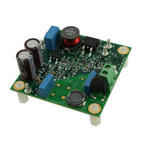
BOARD EVAL LED DRIVER LM3445
Manufacturer
National Semiconductor
Series
PowerWise®r
Specifications of LM3445-208277EV/NOPB
Current - Output / Channel
500mA
Outputs And Type
1, Non-Isolated
Features
Dimmable with Standard TRIAC Dimmer, Power Factor Correction
Voltage - Input
176 ~ 305 VAC
Utilized Ic / Part
LM3445
Lead Free Status / RoHS Status
Lead free / RoHS Compliant
Voltage - Output
-
Other names
LM3445-208277EV
Available stocks
Company
Part Number
Manufacturer
Quantity
Price
Company:

Part Number:
LM3445-208277EV/NOPB
Manufacturer:
National Semiconductor
Quantity:
135


4. Holding Current
This LM3445 High Voltage demo board includes five circuit
blocks (shown below) that work together to draw additional
current from the line at key points in the dimming cycle and
ensure a minimum level of current is drawn from the triac
dimmer at all times. A description of their operation is outlined
below. References are made to Q1 and D9 which can be
found on page 3 schematic.
• Triac edge detect circuit: When the triac fires a sharp edge
is created that can be captured by a properly sized R-C circuit.
The combination of C5/C7 and R3/R4 create a negative pulse
on R2 for a reverse phase dimmer or a positive pulse on R2
for a forward phase dimmer. The pulse polarity determines
which subsequent block will use the signal.
• Forward phase detect/Valley Fill Enable and Valley Fill
triac holding current circuit: With Q3 turning on with each
rectified AC edge from a forward phase dimmer, a duty cycle
divider is created that adjusts the voltage at the anode of D2A.
With the values implemented, the result is an average of ~2V
at the anode of D2A when the rising edge is present on R2
allowing the gate voltage of Q4 to rise and fall with the valley
fill diode cathode voltage V
of D9) and turn Q4 on while the valley fill circuit is providing
power to the load. Additional loading at this time is important
because as the valley fill capacitors are providing current to
the load, no current is being provided by the input through the
triac and a condition for triac mis-fire would otherwise be cre-
ated. When a fast rising edge is not present, Q3 will remain
VF
(V
VF
is connected to the cathode
9
off and the D2A anode voltage and Q4 gate will rise to V
and ensure Q4 will not turn on. The final piece of the circuit is
D2B. The cathode of D9 can rise to ½Vin while the valley fill
capacitors are charging. Since the Q4 gate is rated at ±20
volts a diode is added from the gate to V
at a diode drop above V
mer the waveform edge rises with the line frequency requiring
~4ms to reach the peak. This is not a fast enough edge to
create a signal at the base of Q3 meaning this circuit will nat-
urally not operate when using a reverse phase dimmer or
when no dimmer is present.
• Linear R
LEDs are dimmed to 50% or lower. A variable voltage be-
tween 0 and 5 volts is generated at the Q1 gate by averaging
the DIM pin 5.9kHz square wave. The DIM pin, normally an
input, is used as an output in this implementation as it outputs
a square wave with a duty cycle that varies with triac firing
angle. As the LEDs are dimmed, the voltage at the Q1 gate
will rise pulling a current equal to the Q1 source voltage di-
vided by R36.
• Reverse phase holding current circuit: Adds holding cur-
rent when a reverse phase triac edge is detected. The triac
edge detect R-C creates a negative pulse on the emitter of
Q2 each cycle a reverse phase dimmer is present and dim-
ming. This turns on Q10 and connects R12 to the Q9 pass
FET adding holding current and sharpening the turn-off of the
reverse phase dimmer.
HOLD
Insertion circuit : Adds holding current as
CC
. When using a reverse phase dim-
CC
clamping this point
www.national.com
30103521
CC
Related parts for LM3445-208277EV/NOPB
Image
Part Number
Description
Manufacturer
Datasheet
Request
R

Part Number:
Description:
National Semiconductor [8-Bit D/A Converter]
Manufacturer:
National Semiconductor
Datasheet:
Part Number:
Description:
National Semiconductor [Media Coprocessor]
Manufacturer:
National Semiconductor
Datasheet:
Part Number:
Description:
Digitally Controlled Tone and Volume Circuit with Stereo Audio Power Amplifier, Microphone Preamp Stage and National 3D Sound
Manufacturer:
National Semiconductor
Datasheet:
Part Number:
Description:
Digitally Controlled Tone and Volume Circuit with Stereo Audio Power Amplifier, Microphone Preamp Stage and National 3D Sound
Manufacturer:
National Semiconductor
Datasheet:
Part Number:
Description:
AC97 Rev 2 Codec with Sample Rate Conversion and National 3D Sound
Manufacturer:
National Semiconductor
Part Number:
Description:
Manufacturer:
National Semiconductor
Datasheet:
Part Number:
Description:
Manufacturer:
National Semiconductor
Datasheet:
Part Number:
Description:
General Purpose, Low Voltage, Low Power, Rail-to-Rail Output Operational Amplifiers
Manufacturer:
National Semiconductor
Datasheet:
Part Number:
Description:
8-bit 20 MSPS flash A/D converter.
Manufacturer:
National Semiconductor
Datasheet:
Part Number:
Description:
Low Noise Quad Operational Amplifier
Manufacturer:
National Semiconductor
Datasheet:
Part Number:
Description:
Quad Differential Line Receivers
Manufacturer:
National Semiconductor
Datasheet:
Part Number:
Description:
Quad High Speed Trapezoidal? Bus Transceiver
Manufacturer:
National Semiconductor
Datasheet:
Part Number:
Description:
Dual Line Receiver
Manufacturer:
National Semiconductor
Datasheet:
Part Number:
Description:
TTL to 10k ECL Level Translator with Latch
Manufacturer:
National Semiconductor
Datasheet: