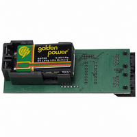
PCA9633DEMO Future Designs Inc, PCA9633DEMO Datasheet - Page 2

PCA9633DEMO
Manufacturer Part Number
PCA9633DEMO
Description
BOARD DEMO FOR PHILIPS PCA9633
Manufacturer
Future Designs Inc
Datasheet
1.PCA9633DEMO.pdf
(6 pages)
Specifications of PCA9633DEMO
Current - Output / Channel
25mA
Outputs And Type
4, Non-Isolated
Voltage - Output
4 V
Features
Dimmable, I²C Interface
Voltage - Input
6 ~ 9V
Utilized Ic / Part
PCA9633
Lead Free Status / RoHS Status
Contains lead / RoHS non-compliant
Other names
622-1004
Mode 4: User Color Mode
Mode 5: Multiple Card Chase Mode
Mode 6: Output Enable Control Mode
H:\Philips\PCA9633DEMO\DOCs\PCA9633 Demo Board User Manual
121905.doc
Allows the user to choose a color by selecting the amount of each LED’s PWM
output as well as the 5
colors at the same time.
Note: If the 5
Uses multiple cards and the group call feature of the PCA9633 to generate a chase
pattern of 2 (yellow/red), 3 (yellow/red/green), or 4 (yellow/red/green/blue) colors
for up to 8 boards (master plus seven slave boards) connected via the RJ45 jacks.
Demonstrates the /Output Enable control pin input that Hi-Zs the LED outputs.
This mode changes the LED diffuser color to purple and blinks all LEDs at the
same rate.
MODE
SELECT
PLUS
MINUS
MODE
SELECT
PLUS
MINUS
MODE
SELECT
PLUS
MINUS
th
Group PWM is set at minimum then no colors will be displayed
th
Next mode
Select color PWM component: Red, Green, Blue, Amber,
or White (5
selected.
More of that color component
Less of that color component
Next mode
Chooses a 2, 3, or 4 color chase pattern.
Faster blinking
Slower blinking
Next mode
Selects frequency (duty cycle fixed at 50%/50%) or duty
cycle (frequency fixed at XX)
Faster frequency (doubles each push) or longer ON duty
cycle
Slower frequency (halves each push) or shorter ON duty
cycle
PCA9633DEMO
group PWM that is used to dim or blink the combined
User Manual
th
Page 2 of 6
Group PWM) flashes as that PWM is
Rev 2


