ADM8845EB-EVALZ Analog Devices Inc, ADM8845EB-EVALZ Datasheet - Page 11
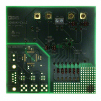
ADM8845EB-EVALZ
Manufacturer Part Number
ADM8845EB-EVALZ
Description
BOARD EVALUATION FOR ADM8845
Manufacturer
Analog Devices Inc
Datasheet
1.ADM8845ACPZ-REEL7.pdf
(20 pages)
Specifications of ADM8845EB-EVALZ
Current - Output / Channel
20mA
Outputs And Type
6, Non-Isolated
Voltage - Output
5.5 V
Features
Charge Pump, Dimmable
Voltage - Input
2.6 ~ 5.5V
Utilized Ic / Part
ADM8845
Lead Free Status / RoHS Status
Lead free / RoHS Compliant


OUTPUT CURRENT CAPABILITY
The ADM8845 can drive up to 30 mA of current to each of the
six LEDs given an input voltage of 2.6 V to 5.5 V. The LED
currents have a maximum current matching of 1% between any
two LED currents. An external resistor, R
current, approximated by the following equation:
To regulate the LED currents properly, sufficient headroom
voltage (compliance) must be present. The compliance refers to
the minimum amount of voltage that must be present across the
internal current sinks to ensure that the desired current and
matching performance can be realized. To ensure that the
desired current is obtained, use the following equation to find
the minimum input voltage required:
where V
compliance is 0.20 V typ and 0.30 V max (see Table 5).
Table 5. I
I
15 mA
20 mA
30 mA
When the ADM8845 charge pump is loaded with 180 mA (six
LEDs at 30 mA/LED), the ambient operating temperature is
reduced (see Figure 21).
AUTOMATIC GAIN CONTROL
The automatic gain control block controls the operation of the
charge pump by selecting the appropriate gain for the charge
pump. This maintains sufficient drive for the LED anodes at
the highest power efficiency over a 2.6 V to 5.5 V input supply
range. The charge pump switching thresholds are described in
Table 6.
Table 6. Charge Pump Switching Thresholds
Gain
1.5× to 2×
2× to 1.5×
1× to 1.5×
1.5× to 1×
LED
R
V
SET
OUT
F
= 120 × (1.18 V/I
is the LED forward voltage. For 20 mA/LED, the
LED
− V
, R
F
R
9.44 kΩ
7.08 kΩ
4.72 kΩ
≥ Compliance
SET
SET
, and Compliance Table
LED
)
Threshold
3.33 V
3.36 V
4.77 V
4.81 V
Typ Compliance
0.17 V
0.20 V
0.34 V
SET
, sets the output
Rev. C | Page 11 of 20
CURRENT MATCHING
The 1% maximum current matching performance is defined by
the following equations:
or
where I
current.
BRIGHTNESS CONTROL WITH A DIGITAL PWM
SIGNAL
PWM brightness control provides the widest brightness control
method by pulsing the white LEDs on and off using the digital
input control pins, CTRL1 and/or CTRL2. PWM brightness
control also removes any chromaticity shifts associated with
changing the white LED current, because the LEDs operate
either at zero current or full current (set by R
The digital PWM signal applied with a frequency of 100 Hz to
200 kHz turns the current control sinks on and off using CTRL1
and/or CTRL2. The average current through the LEDs changes
with the PWM signal duty cycle. If the PWM frequency is much
less than 100 Hz, flicker could be seen in the LEDs. For the
ADM8845, zero duty cycle turns off the LEDs, and a 50% duty
cycle results in an average LED current I
grammed LED current. For example, if R
20 mA/LED, a 50% duty cycle results in an average I
10 mA/LED, I
By applying a digital PWM signal to the digital input control
pins, CTRL1 and/or CTRL2 can adjust the brightness of the sub
and/or main displays. The six white LEDs of the ADM8845 are
organized into two groups: main display, FB1 to FB4, and sub
display, FB5 and FB6. For more information, refer to the Theory
of Operation section.
OR HIGH/LOW
OR HIGH/LOW
PWM INPUT
PWM INPUT
I
Max Matching Error = [(I
Min Matching Error = [(I
AVG
Figure 24. Digital PWM Brightness Control Application Diagram
MAX
R
= (I
SET
is the largest I
I
SET
MAX
LED
CTRL1
CTRL2
+ I
being half the programmed LED current.
1µF
ADM8845
MIN
C1
)/2
1µF
LED
C2
FB1
FB2
FB3
FB4
FB5
FB6
current, and I
MIN
MAX
V
− I
OUT
− I
AVG
AVG
)/I
)/I
LED
SET
AVG
AVG
MIN
being half the pro-
] × 100
is set to program
] × 100
SET
is the smallest I
).
ADM8845
LED
of
C3
2.2µF
LED
Related parts for ADM8845EB-EVALZ
Image
Part Number
Description
Manufacturer
Datasheet
Request
R

Part Number:
Description:
±1.7g Dual-Axis IMEMS Accelerometer Evaluation Board
Manufacturer:
Analog Devices Inc
Datasheet:

Part Number:
Description:
Inertial Sensor Evaluation System
Manufacturer:
Analog Devices Inc
Datasheet:
Part Number:
Description:
Manufacturer:
Analog Devices Inc
Datasheet:
Part Number:
Description:
Manufacturer:
Analog Devices Inc
Datasheet:
Part Number:
Description:
Manufacturer:
Analog Devices Inc
Datasheet:
Part Number:
Description:
Manufacturer:
Analog Devices Inc
Datasheet:
Part Number:
Description:
Manufacturer:
Analog Devices Inc
Datasheet:
Part Number:
Description:
Manufacturer:
Analog Devices Inc
Datasheet:
Part Number:
Description:
Manufacturer:
Analog Devices Inc
Datasheet:
Part Number:
Description:
Manufacturer:
Analog Devices Inc
Datasheet:
Part Number:
Description:
Manufacturer:
Analog Devices Inc
Datasheet:
Part Number:
Description:
Manufacturer:
Analog Devices Inc
Datasheet:
Part Number:
Description:
Manufacturer:
Analog Devices Inc
Datasheet: