MCP1630DM-LED2 Microchip Technology, MCP1630DM-LED2 Datasheet - Page 9
MCP1630DM-LED2
Manufacturer Part Number
MCP1630DM-LED2
Description
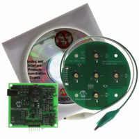
BOARD DEM MCP1630 BOOST MODE LED
Manufacturer
Microchip Technology
Type
DC/DC Switching Converters, Regulators & Controllersr
Specifications of MCP1630DM-LED2
Current - Output / Channel
350mA or 700mA
Outputs And Type
1, Non-Isolated
Voltage - Output
40V
Features
Dimmable
Voltage - Input
9 ~ 16V
Utilized Ic / Part
MCP1630
Input Voltage
9 V
Product
Power Management Modules
Supply Current
700 mA
Core Chip
MCP1630
Topology
Boost
No. Of Outputs
1
Output Current
700mA
Kit Contents
Board
Development Tool Type
Hardware - Eval/Demo Board
For Use With/related Products
MCP1630V, PIC12F683, MCP1702
Lead Free Status / RoHS Status
Lead free / RoHS Compliant
Lead Free Status / RoHS Status
Lead free / RoHS Compliant, Lead free / RoHS Compliant
Available stocks
Company
Part Number
Manufacturer
Quantity
Price
Company:

Part Number:
MCP1630DM-LED2
Manufacturer:
Microchip Technology
Quantity:
135


1.1
1.2
© 2007 Microchip Technology Inc.
INTRODUCTION
FEATURES
The MCP1630 Boost Mode LED Driver Demo Board is a step-up, switch-mode, dc-dc
converter used for power LED applications. The demo board provides a 350 mA or
700 mA constant current source with a jumper selection. Other output currents can be
obtained with minor modifications to the board.
The MCP1630 Boost Mode LED Driver Demo Board utilizes Microchip's MCP1630V
high-speed pulse width modulator. The 8-pin MCP1630V device contains the analog
components necessary for an analog switch-mode control loop including an error
amplifier, PWM comparator, and a high current driver pin. The switching frequency and
maximum duty cycle for the MCP1630V are determined by an external clock source.
An 8-pin PIC12F683 microcontroller is used to provide a 500 kHz switching clock for
the MCP1630. In addition, the PIC12F683 firmware supervises the circuit output
voltage and can optionally dim the LEDs when a potentiometer is attached.
In this demo application, the MCP1630V device is used for Average Current mode
control using a voltage boost circuit. A ramp generator provides a reference signal to
the MCP1630V comparator. The ramp signal and error amplifier output voltage
determine the PWM duty cycle for the voltage boost circuit. The MCP1630V device is
used because its error amplifier provides a higher output voltage range than the
MCP1630 device (2.7V vs. 0.9V).
The MCP1630 Boost Mode LED Driver Demo Board has the following features:
• Compact size with high output power
• High efficiency over entire operating input voltage range
• Selectable output current: 350 mA or 700 mA
• Maximum output power: 30W
• Optional software dimming control
• Factory programmed source code provided
• Switching frequency, maximum duty cycle, and MCP1630 reference voltage can
• Additional application functions can be provided in firmware
be modified in firmware
Note:
Chapter 1. Product Overview
MCP1630 is used throughout this document for both the MCP1630 and
MCP1630V devices.
MCP1630 BOOST MODE LED DRIVER
DEMO BOARD USER’S GUIDE
DS51665B-page 5
Related parts for MCP1630DM-LED2
Image
Part Number
Description
Manufacturer
Datasheet
Request
R

Part Number:
Description:
BOARD DEMO BOOST AUTO INPUT
Manufacturer:
Microchip Technology
Datasheet:

Part Number:
Description:
BOARD CONV DEMO MCP1630 TRPL-OUT
Manufacturer:
Microchip Technology
Datasheet:

Part Number:
Description:
BOARD DEMO FOR MCP1630
Manufacturer:
Microchip Technology
Datasheet:

Part Number:
Description:
BOARD DEMO MCP1630 BIAS SUPPLY
Manufacturer:
Microchip Technology
Datasheet:

Part Number:
Description:
BOARD DEMO BOOST COUPLED INDUCTR
Manufacturer:
Microchip Technology
Datasheet:

Part Number:
Description:
Manufacturer:
Microchip Technology Inc.
Datasheet:
Part Number:
Description:
Manufacturer:
Microchip Technology Inc.
Datasheet:
Part Number:
Description:
Manufacturer:
Microchip Technology Inc.
Datasheet:
Part Number:
Description:
Manufacturer:
Microchip Technology Inc.
Datasheet:
Part Number:
Description:
Manufacturer:
Microchip Technology Inc.
Datasheet:
Part Number:
Description:
Manufacturer:
Microchip Technology Inc.
Datasheet: