CDB4352 Cirrus Logic Inc, CDB4352 Datasheet
CDB4352
Specifications of CDB4352


Related parts for CDB4352


CDB4352 Summary of contents
Page 1
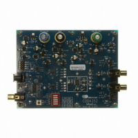
... S/PDIF Input (CS8416) Reset http://www.cirrus.com Description The CDB4352 evaluation board is an excellent means for quickly evaluating the CS4352 24-bit, high-perfor- mance stereo D/A converter. Evaluation requires an analog signal analyzer, a digital signal source, and a power supply. Analog line-level outputs are provided via RCA phono jacks ...
Page 2
... TABLE OF CONTENTS 1. CDB4352 SYSTEM OVERVIEW ............................................................................................................ 4 2. CS4352 DIGITAL-TO-ANALOG CONVERTER ..................................................................................... 4 3. CS8416 DIGITAL AUDIO RECEIVER .................................................................................................... 4 4. INPUT FOR CLOCKS AND DATA ......................................................................................................... 4 5. POWER SUPPLY CIRCUITRY ............................................................................................................... 4 6. GROUNDING AND POWER SUPPLY DECOUPLING .......................................................................... 5 7. HARDWARE CONTROL ........................................................................................................................ 5 8. ANALOG OUTPUT FILTERING ............................................................................................................. 5 9. PERFORMANCE PLOTS ....................................................................................................................... 6 10. DESIGN NOTE ................................................................................................................................... 11 11 ...
Page 3
... Figure 38. Top Side ................................................................................................................................... 19 Figure 39. Bottom Side ............................................................................................................................. 20 LIST OF TABLES Table 1. System Connections .................................................................................................................... 5 Table 2. CDB4352 Jumper Settings .......................................................................................................... 11 DS684DB1 CDB4352 3 ...
Page 4
... CDB4352 SYSTEM OVERVIEW The CDB4352 evaluation board is an excellent means of quickly evaluating the CS4352. The CS8416 digital audio interface receiver provides an easy interface to digital audio signal sources including the majority of digital audio test equipment. The evaluation board also allows the user to supply external PCM clocks and data through a header for system development ...
Page 5
... CS4352 as possible. Extensive use of ground plane fill in the evaluation board yields large reductions in radiated noise. 7. HARDWARE CONTROL The CDB4352 is controlled through settings on switch S1. This allows for configuration of the board without a PC. A switch is provided for CS8416 MCLK speed, clock and data source for the board, and the hardware mode config- uration of the CS4352. ...
Page 6
... Figure 4. FFT (48 kHz Out-of-Band, No Input) +0 -10 -20 -30 - -60 A -70 -80 -90 -100 -110 -120 -100 2k 5k 10k 20k Figure 6. 48 kHz, THD+N vs. Level CDB4352 100 200 500 10k Hz 40k 60k 80k 100k Hz -80 -60 -40 -20 dBFS DS684DB1 20k 120k +0 ...
Page 7
... Figure 10. 48 kHz, Impulse Response +0 -10 -20 -30 -40 - -70 -80 A -90 -100 -110 -120 -130 -140 10k 20k Figure 12. FFT (96 kHz, -60 dB) CDB4352 100 200 500 10k Hz 1m 1.5m 2m 2.5m sec 100 200 500 10k Hz 20k 3m 20k 7 ...
Page 8
... Figure 14. FFT (96 kHz Out-of-Band, No Input) +0 -10 -20 -30 - -60 A -70 -80 -90 -100 -110 2k 5k 10k 20k -120 -100 Figure 16. 96 kHz, THD+N vs. Level + -40 - Figure 18. 96 kHz, Frequency Response CDB4352 40k 60k 80k 100k Hz -80 -60 -40 -20 dBFS 100 200 500 10k Hz DS684DB1 120k +0 20k ...
Page 9
... Figure 22. FFT (192 kHz, -60 dB) +0 -10 -20 -30 -40 -50 - -70 -80 A -90 -100 -110 -120 -130 -140 20k 2k 5k 10k 20k Figure 24. FFT (192 kHz Out-of-Band, No Input) CDB4352 500u 750u 1m 1.25m sec 100 200 500 10k Hz 40k 60k 80k 100k Hz 1.5m 20k 120k 9 ...
Page 10
... Figure 26. 192 kHz, THD+N vs. Level + -40 - Figure 28. 192 kHz, Frequency Response 3 2.5 2 1.5 1 500m V 0 -500m -1 -1 10k 20k Figure 30. 192 kHz, Impulse Response CDB4352 -80 -60 -40 -20 dBFS 100 200 500 10k Hz 200u 400u 600u sec DS684DB1 +0 20k ...
Page 11
... CS8416 *1 = open position 8416 MCLK is 256xFs 128xFs * closed Position 3,4,5: see CS4352 datasheet - Enables reset for CS4352 and CS8416 when pressed *LED Bypasses muting to turn on LED MUTE Table 2. CDB4352 Jumper Settings CDB4352 FUNCTION SELECTED Normal muting circuit 11 ...
Page 12
Reset Circuit MCLK SCLK 8416 Digital LRCK SDIN Audio Receiver Figure 35 PCM Inputs Figure 34 Hardware Switch Power Figure 34 Figure 36 CS4352 Figure 32 Figure 31. System Block Diagram and Signal Flow Channel A Outputs and Mute ...
Page 13
Figure 32. CS4352 ...
Page 14
Figure 33. Analog Outputs ...
Page 15
Figure 34. PCM Input Headers ...
Page 16
Figure 35. CS8416 S/PDIF Input ...
Page 17
Figure 36. Power ...
Page 18
Figure 37. Silkscreen Top ...
Page 19
Figure 38. Top Side ...
Page 20
Figure 39. Bottom Side ...
Page 21
... OTHER AGENTS FROM ANY AND ALL LIABILITY, INCLUDING ATTORNEYS’ FEES AND COSTS, THAT MAY RESULT FROM OR ARISE IN CONNECTION WITH THESE USES. Cirrus Logic, Cirrus, and the Cirrus Logic logo designs are trademarks of Cirrus Logic, Inc. All other brand and product names in this document may be trademarks or service marks of their respective owners. DS684DB1 Changes www.cirrus.com. CDB4352 21 ...