MCP4725DM-PTPLS Microchip Technology, MCP4725DM-PTPLS Datasheet - Page 9
MCP4725DM-PTPLS
Manufacturer Part Number
MCP4725DM-PTPLS
Description
BOARD DAUGHTER PICTAIL MCP4725
Manufacturer
Microchip Technology
Specifications of MCP4725DM-PTPLS
Number Of Dac's
1
Number Of Bits
12
Outputs And Type
1, Single Ended
Sampling Rate (per Second)
100k ~ 3.4M
Data Interface
I²C
Settling Time
6µs
Dac Type
Voltage
Voltage Supply Source
Single
Operating Temperature
-40°C ~ 125°C
Utilized Ic / Part
MCP4725
Silicon Manufacturer
Microchip
Application Sub Type
DAC
Kit Application Type
Data Converter
Silicon Core Number
MCP4725
Silicon Family Name
PICtail
Lead Free Status / RoHS Status
Lead free / RoHS Compliant
Available stocks
Company
Part Number
Manufacturer
Quantity
Price
Company:

Part Number:
MCP4725DM-PTPLS
Manufacturer:
Microchip Technology
Quantity:
135


1.1
1.2
© 2008 Microchip Technology Inc.
INTRODUCTION
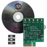
DESCRIPTION OF THE MCP4725 PICtail™ Plus DAUGHTER BOARD
The following sections provide an overview of the MCP4725 PICtail™ Plus Daughter
Board and demonstrate how to use (a) the MCP4725 device in a 16-bit MCU environ-
ment and (b) evaluate the MCP4725 device features using the PICkit™ Serial Analyzer
(P/N: DV164122). The MCP4725 PICtail™ Plus Daughter Board is designed to work
with both the Explorer 16 Development Board (P/N: DV164033) and the PICkit
Analyzer (P/N: DV164122).
The following topics are covered:
• Description of the MCP4725 PICtail™ Plus Daughter Board
• How to use the MCP4725 PICtail™ Plus Daughter Board with the Explorer 16
• How to use MCP4725 PICtail™ Plus Daughter Board with the PICkit
The MCP4725 PICtail™ Plus Daughter Board (P/N MCP4725DM-PTPLS) contains an
MCP4725 12-bit Digital-to-Analog Converter (DAC). This daughter board has the fol-
lowing two interfaces:
• Explorer 16 Starter Kit (P/N: DV164033) for 16-bit MCU environment
• PICkit™ Serial Analyzer (P/N: DV164122) for reading and writing the DAC
The user can connect this daughter board to one of the above tools and perform their
own experiments.
The board has test points for SDL, SDA, and V
these test points (to SCL, SDA, V
ine the data communications through the I
output (V
1.2.1
The I
• Device Code: ‘1100’
• A2, A1, A0 Address Bits: ‘00X’, where X is for the A0 bit which is determined by
Note that the first two address bits (A2 and A1) are programmed at factory during
device production and A0 bit is programmed by the user during applications. The A2
and A1 address bits of the MCP4725 device used for the MCP4725 PICtail™ Plus
Daughter Board are programmed at the factory to ‘00’. The JMP1 connector on the
MCP4725 PICtail™ Plus Daughter Board selects the A0 bit. The following conditions
show the A0 bit selection:
• A0 bit = ‘1’ if JMP1 is connected to V
• A0 bit = ‘0’ if JMP1 is connected to V
• Address bits A2, A1 = ‘00’
Chapter 1. Quick Start Instructions
Starter Kit
Analyzer
register and observing the DAC output
the logic state of the A0 pin
2
C device code and address bits of the MCP4725 device are:
OUT
I
2
C Address Bits and A0 Address Bit Selection
). Refer to Appendix A. “Schematic and Layouts”
MCP4725 PICtail™ Plus DAUGHTER
OUT
) or Digital Multimeter to V
BOARD USER’S GUIDE
DD
SS
2
C
(Default setting)
™
bus line and observe the resulting DAC
OUT
. By connecting an oscilloscope to
OUT
, the user can exam-
™
DS51722A-page 5
Serial
™
Serial
Related parts for MCP4725DM-PTPLS
Image
Part Number
Description
Manufacturer
Datasheet
Request
R

Part Number:
Description:
Manufacturer:
Microchip Technology Inc.
Datasheet:
Part Number:
Description:
Manufacturer:
Microchip Technology Inc.
Datasheet:
Part Number:
Description:
Manufacturer:
Microchip Technology Inc.
Datasheet:
Part Number:
Description:
Manufacturer:
Microchip Technology Inc.
Datasheet:
Part Number:
Description:
Manufacturer:
Microchip Technology Inc.
Datasheet:
Part Number:
Description:
Manufacturer:
Microchip Technology Inc.
Datasheet:
Part Number:
Description:
Manufacturer:
Microchip Technology Inc.
Datasheet:
Part Number:
Description:
Manufacturer:
Microchip Technology Inc.
Datasheet: