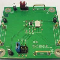
NCP1521UEVB ON Semiconductor, NCP1521UEVB Datasheet - Page 9

NCP1521UEVB
Manufacturer Part Number
NCP1521UEVB
Description
EVAL BOARD FOR NCP1521U
Manufacturer
ON Semiconductor
Specifications of NCP1521UEVB
Design Resources
NCP1521UEVB BOM NCP1521UEVB Schematic NCP1521UEVB Gerber Files
Main Purpose
DC/DC, Step Down
Outputs And Type
1, Non-Isolated
Voltage - Output
0.9 ~ 3.3 V
Current - Output
600mA
Voltage - Input
3.6V
Regulator Topology
Buck
Frequency - Switching
1.5MHz
Board Type
Fully Populated
Utilized Ic / Part
NCP1521
Lead Free Status / RoHS Status
Lead free / RoHS Compliant
Power - Output
-
Lead Free Status / Rohs Status
Lead free / RoHS Compliant
For Use With/related Products
NCP1521U
Other names
NCP1521UEVBOS
Cycle-by-Cycle Current Limitation
is used to realize cycle-by-cycle current limit protection.
The comparator compares the LX pin voltage with the
reference voltage, which is biased by a constant current. If
the inductor current reaches the limit, the I
detects the LX voltage falling below the reference voltage
and releases the signal to turn off the switch Q1. The
cycle-by-cycle current limit is set at 1200 mA (nom).
Short Circuit Protection
the inductor current. The duty-cycle is minimum and the
consumption on the input line is 300 mA (Typ). When the
short circuit condition is removed, the device returns to the
normal mode of operation.
Soft-Start
inrush current when the device is initially enabled.
Soft-start is implemented by gradually increasing the
reference voltage until it reaches the full reference voltage.
During startup, a pulsed current source charges the internal
soft-start
reference voltage. When the voltage across the capacitor
ramps up to the nominal reference voltage, the pulsed
current source will be switched off and the reference
voltage will switch to the regular reference voltage.
Shutdown Mode
the NCP1521 will be disabled. In shutdown mode, the
internal reference, oscillator and most of the control
circuitries are turned off. Therefore, the typical current
From the block diagram (Figure 3), an I
When the output is shorted to ground, the device limits
The NCP1521 uses soft-start (300 ms Typ) to limit the
When the EN pin has a voltage applied of less than 0.4 V,
capacitor to provide gradually increasing
LIM
LIM
comparator
comparator
http://onsemi.com
NCP1521
9
consumption will be 0.3 mA (typical value). Applying a
voltage above 1.2 V to EN pin will enable the device for
normal operation. The typical threshold is around 0.7 V.
The device will go through soft-start to normal operation,
however, the EN pin should be tied low while the input
voltage on V
Thermal Shutdown
protect the integrated circuit in the event that the maximum
junction temperature is exceeded. If the junction
temperature exceeds 160_C, the device shuts down. In this
mode switch Q1 and Q2 and the control circuits are all
turned off. The device restarts in soft-start after the
temperature drops below 135_C. This feature is provided
to prevent catastrophic failures from accidental device
overheating, and it is not intended as a substitute for proper
heatsinking.
Low Dropout Operation
difference. The NCP1521 can operate at 100% duty cycle.
In this mode the PMOS (Q1) switches completely on.
be calculated as:
•
•
•
•
Internal Thermal Shutdown circuitry is provided to
The NCP1521 offers a low input to output voltage
The minimum input voltage to maintain regulation can
V
I
R
R
OUT
V IN(min) + V OUT(max)
DS(on)
INDUCTOR
OUT
: Max Output Current
: Output Voltage (Volts)
: P-Channel Switch R
IN
: Inductor Resistance (DCR)
) (I OUT
pin is rising up.
(R DS(on) ) R INDUCTOR ))
DS(on)
(eq. 1)


