NCP1423EVB ON Semiconductor, NCP1423EVB Datasheet - Page 2
NCP1423EVB
Manufacturer Part Number
NCP1423EVB
Description
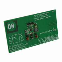
EVAL BOARD FOR NCP1423
Manufacturer
ON Semiconductor
Specifications of NCP1423EVB
Design Resources
NCP1423 Demo Board BOM NCP1423EVB Gerber Files NCP1423EVB Schematic
Main Purpose
DC/DC, Step Up
Outputs And Type
1, Non-Isolated
Voltage - Output
3.3V
Current - Output
400mA
Voltage - Input
2.5V
Regulator Topology
Boost
Frequency - Switching
600kHz
Board Type
Fully Populated
Utilized Ic / Part
NCP1423
Lead Free Status / RoHS Status
Lead free / RoHS Compliant
Power - Output
-
Lead Free Status / Rohs Status
Lead free / RoHS Compliant
For Use With/related Products
NCP1423
Other names
NCP1423EVBOS


Test Procedure:
3.3V Output Version
1. Setup the Equipments
2. Connect the equipment and the demo board. (Figure 1)
3. Setup the Demo Board Jumpers. (Refer to table on board)
4. Measuring Result:
5. LBO Test
Set the power supply voltage to 2.5 V.
Set the electronic load loading current to 50 mA.
DMM
DMM
Connect a power supply with 4-wire sensing across V
Connect an electronic load across V
Remove the jumper link from:
JP1 to Enable the device
JP2 to Enable Auto Discharge
a. For I
V
I
b. For I
V
I
Set V
to High as V
IN
IN
OUT
OUT
= 70 mA to 80 mA
= 490 mA to 540 mA
= 3.15 V to 3.45 V
= 3.15 V to 3.45 V
1
2
BAT
(A) as ammeter, measures the input current (I
(V) as voltmeter, measures the output voltage (V
OUT
OUT
Oscilloscope (optional)
low, between 1.1 V and 1.3 V; measure the voltage at LBO pin. LBO voltage status will change from Low
= 50 mA, measure
= 350 mA, measure
DC Power Supply
BAT
is changed from low to high.
OUT
Table 1: Required Equipment
and GND.
One NCP1423 Evaluation Board
Ammeter (DMM
IN
BAT
).
OUT
and GND.
).
1
)
Voltmeter (DMM
Electronic Load
2
)
Related parts for NCP1423EVB
Image
Part Number
Description
Manufacturer
Datasheet
Request
R

Part Number:
Description:
400 Ma Sync-rect Pfm Stepup Dcdc Converter With Truecutoff And Ringkiller
Manufacturer:
ON Semiconductor
Datasheet:
Part Number:
Description:
ON Semiconductor [VOLTAGE REGULATOR]
Manufacturer:
ON Semiconductor
Datasheet:
Part Number:
Description:
357-036-542-201 CARDEDGE 36POS DL .156 BLK LOPRO
Manufacturer:
ON Semiconductor
Datasheet:
Part Number:
Description:
357-036-542-201 CARDEDGE 36POS DL .156 BLK LOPRO
Manufacturer:
ON Semiconductor
Datasheet:
Part Number:
Description:
357-036-542-201 CARDEDGE 36POS DL .156 BLK LOPRO
Manufacturer:
ON Semiconductor
Datasheet:
Part Number:
Description:
357-036-542-201 CARDEDGE 36POS DL .156 BLK LOPRO
Manufacturer:
ON Semiconductor
Datasheet:
Part Number:
Description:
357-036-542-201 CARDEDGE 36POS DL .156 BLK LOPRO
Manufacturer:
ON Semiconductor
Datasheet:
Part Number:
Description:
357-036-542-201 CARDEDGE 36POS DL .156 BLK LOPRO
Manufacturer:
ON Semiconductor
Datasheet:
Part Number:
Description:
357-036-542-201 CARDEDGE 36POS DL .156 BLK LOPRO
Manufacturer:
ON Semiconductor
Datasheet:
Part Number:
Description:
357-036-542-201 CARDEDGE 36POS DL .156 BLK LOPRO
Manufacturer:
ON Semiconductor
Datasheet:
Part Number:
Description:
357-036-542-201 CARDEDGE 36POS DL .156 BLK LOPRO
Manufacturer:
ON Semiconductor
Datasheet:
Part Number:
Description:
357-036-542-201 CARDEDGE 36POS DL .156 BLK LOPRO
Manufacturer:
ON Semiconductor
Datasheet:
Part Number:
Description:
Manufacturer:
ON Semiconductor
Datasheet:
Part Number:
Description:
Manufacturer:
ON Semiconductor
Datasheet: