LM2653-ADJEVAL National Semiconductor, LM2653-ADJEVAL Datasheet
LM2653-ADJEVAL
Specifications of LM2653-ADJEVAL


Related parts for LM2653-ADJEVAL

LM2653-ADJEVAL Summary of contents
Page 1
... At light loads, the LM2653 enters a low power hysteretic or “sleep” mode to keep the efficiency high. In many applications, the efficiency still exceeds 80 load. A shutdown pin is available to disable the LM2653 and reduce the supply current to 7µA. All the power, control, and drive functions are integrated within the ICs ...
Page 2
... Absolute Maximum Ratings If Military/Aerospace specified devices are required, please contact the National Semiconductor Sales Office/ Distributors for availability and specifications. Input Voltage PGOOD Pin Voltage Feedback Pin Voltage Power Dissipation (T =25˚C), A (Note 2) Junction Temperature Range Storage Temperature Range Electrical Characteristics Specifications with standard typeface are for T Range ...
Page 3
Electrical Characteristics Specifications with standard typeface are for T Range 10V unless otherwise specified. IN Symbol Parameter V Bootstrap Regulator Voltage I BOOT G Error Amplifier M Transconductance A Error Amplifier Voltage Gain V I Error Amplifier Source ...
Page 4
... A JA allows the safe dissipation of more power. The Absolute Maximum power dissipation must be derated by 7.14 mW per ˚C above 25˚C ambient. The LM2653 actively limits its junction temperatures to about 165˚C. Note 3: The human body model is a 100 pF capacitor discharged through a 1.5 kΩ resistor into each pin. ...
Page 5
Typical Performance Characteristics R vs Junction Temperature SW(ON) Current Limit vs Junction Temperature (V Sleep Mode Threshold vs Output Voltage (V (Continued) Current Limit vs Input Voltage (V 10104924 = 2.5V) Reference Voltage vs Junction Temperature OUT 10104928 = 5V) ...
Page 6
... PGND www.national.com 16-Lead TSSOP (MTC) 10104914 Top View Order Number LM2653MTC-ADJ See NS Package Number MTC16 Switched-node connection, which is connected with the source of the internal high-side MOSFET. Main power supply input pin. Connected to the drain of the high-side MOSFET. Bootstrap capacitor connection for high-side gate drive. ...
Page 7
... Block Diagram Operation The LM2653 operates in a constant frequency (300 kHz), current-mode PWM for moderate to heavy loads; and it automatically switches to hysteretic mode for light loads. In hysteretic mode, the switching frequency is reduced to keep the efficiency high. MAIN OPERATION When the load current is higher than the sleep mode thresh- old, the part is always operating in PWM mode ...
Page 8
Operation (Continued) CAPACITOR section for more information.) Toggling the in- put supply voltage or the shutdown pin can reset the device from the latched protection mode. Design Procedure This section presents guidelines for selecting external com- ponents. INPUT CAPACITOR A ...
Page 9
... OUT IN IN and V and V in volts). IN OUT The total loop gain G is approximately 500 amperes amplifier is used inside the LM2653. The output resis- tor R of the Gm amplifier is about 80kΩ together with R give a lag compensation to roll off the gain 1/(2πC (R ...
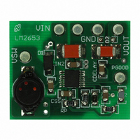
Page 10
Typical PC Board Layout: (2X Size) www.national.com Component Placement Guide Component Side PC Board Layout 10 10104919 10104920 ...
Page 11
Typical PC Board Layout: (2X Size) (Continued) Solder Side PC Board Layout 11 10104921 www.national.com ...
Page 12
... Deutsch Tel: +49 (0) 69 9508 6208 English www.national.com Français Tel: +33 ( 8790 16-Lead TSSOP (MTC) Order Number LM2653MTC-ADJ NS Package Number MTC16 2. A critical component is any component of a life support device or system whose failure to perform can be reasonably expected to cause the failure of the life support device or system affect its safety or effectiveness ...