LM2704EV National Semiconductor, LM2704EV Datasheet - Page 2
LM2704EV
Manufacturer Part Number
LM2704EV
Description
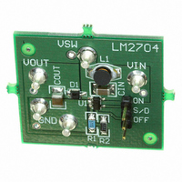
BOARD EVALUATION LM2704
Manufacturer
National Semiconductor
Specifications of LM2704EV
Main Purpose
DC/DC, Step Up
Outputs And Type
1, Non-Isolated
Voltage - Output
20V
Current - Output
550mA
Voltage - Input
2.2 ~ 7V
Regulator Topology
Boost
Board Type
Fully Populated
Utilized Ic / Part
LM2704
Silicon Manufacturer
National
Silicon Core Number
LM2704
Kit Application Type
Power Management - Voltage Regulator
Application Sub Type
Step Up DC/DC Converter
Kit Contents
LM2604 IC Step Up Converter
Rohs Compliant
No
Lead Free Status / RoHS Status
Not applicable / Not applicable
Power - Output
-
Frequency - Switching
-


www.national.com
Connection Diagram
Ordering Information
Pin Description/Functions
SW(Pin 1): Switch Pin. This is the drain of the internal
NMOS power switch. Minimize the metal trace area con-
nected to this pin to minimize EMI.
GND(Pin 2): Ground Pin. Tie directly to ground plane.
FB(Pin 3): Feedback Pin. Set the output voltage by selecting
values for R1 and R2 using:
LM2704MFX-ADJ
LM2704MF-ADJ
Order Number
Pin
1
2
3
4
5
SHDN
Name
GND
SW
V
FB
IN
Package Type
SOT23-5
SOT23-5
Power Switch input.
Ground.
Output voltage feedback input.
Shutdown control input, active low.
Analog and Power input.
T
Jmax
= 125˚C, θ
NSC Package Drawing
Top View
MA05B
MA05B
SOT23-5
JA
2
= 220˚C/W (Note 2)
Connect the ground of the feedback network to an AGND
plane which should be tied directly to the GND pin.
SHDN(Pin 4): Shutdown Pin. The shutdown pin is an active
low control. Tie this pin above 1.1V to enable the device. Tie
this pin below 0.3V to turn off the device.
V
as close to the device as possible.
IN
(Pin 5): Input Supply Pin. Bypass this pin with a capacitor
Function
Top Mark
20031502
S28B
S28B
1000 Units, Tape and Reel
3000 Units, Tape and Reel
Supplied As
Related parts for LM2704EV
Image
Part Number
Description
Manufacturer
Datasheet
Request
R

Part Number:
Description:
Micropower Step-up Dc/dc Converter With 550ma Peak Current Limit
Manufacturer:
National Semiconductor Corporation
Datasheet:
Part Number:
Description:
Micropower Step-up DC/DC Converter with 550mA Peak Current Limit
Manufacturer:
NSC [National Semiconductor]
Datasheet:

Part Number:
Description:
National Semiconductor [8-Bit D/A Converter]
Manufacturer:
National Semiconductor
Datasheet:
Part Number:
Description:
National Semiconductor [Media Coprocessor]
Manufacturer:
National Semiconductor
Datasheet:
Part Number:
Description:
Digitally Controlled Tone and Volume Circuit with Stereo Audio Power Amplifier, Microphone Preamp Stage and National 3D Sound
Manufacturer:
National Semiconductor
Datasheet:
Part Number:
Description:
Digitally Controlled Tone and Volume Circuit with Stereo Audio Power Amplifier, Microphone Preamp Stage and National 3D Sound
Manufacturer:
National Semiconductor
Datasheet:
Part Number:
Description:
AC97 Rev 2 Codec with Sample Rate Conversion and National 3D Sound
Manufacturer:
National Semiconductor
Part Number:
Description:
Manufacturer:
National Semiconductor
Datasheet:
Part Number:
Description:
Manufacturer:
National Semiconductor
Datasheet:
Part Number:
Description:
General Purpose, Low Voltage, Low Power, Rail-to-Rail Output Operational Amplifiers
Manufacturer:
National Semiconductor
Datasheet:
Part Number:
Description:
8-bit 20 MSPS flash A/D converter.
Manufacturer:
National Semiconductor
Datasheet:
Part Number:
Description:
Low Noise Quad Operational Amplifier
Manufacturer:
National Semiconductor
Datasheet:
Part Number:
Description:
Quad Differential Line Receivers
Manufacturer:
National Semiconductor
Datasheet:
Part Number:
Description:
Quad High Speed Trapezoidal? Bus Transceiver
Manufacturer:
National Semiconductor
Datasheet: