LM25574EVAL National Semiconductor, LM25574EVAL Datasheet

BOARD EVALUATION FOR LM25574

LM25574EVAL

Manufacturer Part Number
LM25574EVAL
Description
BOARD EVALUATION FOR LM25574
Manufacturer
National Semiconductor
Series
PowerWise®, SIMPLE SWITCHER®r
Datasheets

Specifications of LM25574EVAL

Main Purpose
DC/DC, Step Down
Outputs And Type
1, Non-Isolated
Voltage - Output
5V
Current - Output
500mA
Voltage - Input
7 ~ 42V
Regulator Topology
Buck
Frequency - Switching
300kHz
Board Type
Fully Populated
Utilized Ic / Part
LM25574
Lead Free Status / RoHS Status
Not applicable / Not applicable
Power - Output
-
Other names
*LM25574EVAL
© 2007 National Semiconductor Corporation
LM25574 Evaluation Board
Introduction
The LM25574 evaluation board is designed to provide the
design engineer with a fully functional power converter based
on Emulated Current Mode Control to evaluate the LM25574
regulator IC. The evaluation board provides a 5V output with
a 0.5A current capability. The ultra-wide input voltage ranges
from 7V to 42V. The design operates at 300kHz, a good com-
promise between conversion efficiency and solution size. The
printed circuit board consists of 2 layers of 2 ounce copper on
FR4 material with a thickness of 0.06 inches. This application
note contains the evaluation board schematic, Bill-of-Materi-
als (BOM) and a quick setup procedure. Refer to the LM25574
datasheet for complete circuit design information.
Evaluation Board Schematic
Powering and Loading
Considerations
Read this entire page prior to attempting to power the evalu-
ation board.
QUICK SETUP PROCEDURE
Step 1: Set the power supply current limit to 0.6A. Turn off
the power supply. Connect the power supply to the Vin ter-
minals.
Step 2: Connect the load, with a 0.5A capability, to the Vout
terminals. Positive connection to J2 and negative connection
to J3.
Step 3: The SD pin should be left open for normal operation.
Step 4: Set Vin to 24V with no load applied. Vout should be
in regulation with a nominal 5V output.
300069
National Semiconductor
Application Note 1577
Robert Bell
January 2007
The performance of the evaluation board is as follows:
Input Range: 7 to 42V
Output Voltage: 5V
Output Current: 0 to 0.5A
Frequency of Operation: 300 KHz
Board Size: 2.1 X 1 X 0.4 inches
Load Regulation: 1%
Line Regulation: 0.1%
Over Current Limiting
Step 5: Slowly increase the load while monitoring the output
voltage, Vout should remain in regulation with a nominal 5V
output as the load is increased up to 0.5 Amps.
Step 6: Slowly sweep the input voltage from 7 to 42V, Vout
should remain in regulation with a nominal 5V output.
Step 7: Temporally short the SD pin to GND to check the
shutdown function.
Step 8: Increase the load beyond the normal range to check
current limiting. The output current should limit at approxi-
mately 0.7A. The power supply (Vin source) current limit may
need to be increased for this step. Cooling is critical during
this step.
AIR FLOW
Prolonged operation with high input voltage at full power will
cause the thermal shutdown circuit within the regulator IC to
www.national.com
30006901

Related parts for LM25574EVAL

LM25574EVAL Summary of contents

Page 1

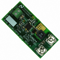
... Positive connection to J2 and negative connection to J3. Step 3: The SD pin should be left open for normal operation. Step 4: Set Vin to 24V with no load applied. Vout should be in regulation with a nominal 5V output. © 2007 National Semiconductor Corporation National Semiconductor Application Note 1577 Robert Bell January 2007 ...

Page 2

A stand-alone fan with at lease 200 LFM should al- ways be provided. POWERING UP Using the shutdown pin provided will allow powering up the source supply with the current level set low suggested that the load ...

Page 3

... CAPACITOR, CER, TDK CAPACITOR, CER, TDK DIODE, 60V, CENTRAL INDUCTOR, COOPER NOT USED NOT USED RESISTOR RESISTOR RESISTOR RESISTOR REGULATOR, NATIONAL SEMICONDUCTOR 3 Value 1µ, 100V 470p, 100V 0.01µ, 100V 0.022µ, 100V 0.022µ, 100V 0.47µ, 16V 22µ, 16V 100µ ...

Page 4

PCB Layout www.national.com Component Side Solder Side Silkscreen 4 30006905 30006906 30006907 ...

Page 5

Notes 5 www.national.com ...

Page 6

... National Semiconductor and the National Semiconductor logo are registered trademarks of National Semiconductor Corporation. All other brand or product names may be trademarks or registered trademarks of their respective holders. ...

Related keywords