LM2833ZMYEVAL National Semiconductor, LM2833ZMYEVAL Datasheet
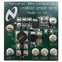
BOARD EVAL LM2833 3MHZ 10MSOP

LM2833ZMYEVAL

Manufacturer Part Number
LM2833ZMYEVAL
Description
BOARD EVAL LM2833 3MHZ 10MSOP
Manufacturer
National Semiconductor
Datasheets

Specifications of LM2833ZMYEVAL

Main Purpose
DC/DC, Step Down
Outputs And Type
1, Non-Isolated
Voltage - Output
1.2V
Current - Output
3A
Voltage - Input
3 ~ 5.5V
Regulator Topology
Buck
Frequency - Switching
3MHz
Board Type
Fully Populated
Utilized Ic / Part
LM2833
Silicon Manufacturer
National
Silicon Core Number
LM2833
Kit Application Type
Power Management - Voltage Regulator
Application Sub Type
Step Down Switching Regulator
Kit Contents
Board, Doc
Lead Free Status / RoHS Status
Lead free / RoHS Compliant
Power - Output
-
© 2009 National Semiconductor Corporation
LM2833Z LLP Demo Board
Introduction
The LM2833Z LLP Demo Board is designed to demonstrate
the capabilities of the LM2833Z 3MHz switching regulator in
an LLP-10 package.
The demo board is configured to provide an output of 1.2V at
up to 3A from an input voltage range of 3V to 5.5V. The board
is thermally optimized with the small solution size of 1.2" X
1.1", shown in the demo board schematic in Figure 1. The
output voltage can be configured to a different value by
changing the ratio between R1 and R2 according to the fol-
lowing equation:
The feedback voltage VFB is regulated at 0.60V typically.
The board has C5 reserved for two purposes given different
application scenarios. First, at high VOUT applications, the
control loop bandwidth is not as large as at low VOUT. Adding
C5 at high VOUT can significantly improve the load step re-
sponse by boosting the loop bandwidth without significantly
compromising phase margin. Secondly, it also helps to mini-
mize output voltage overshoot during sluggish startup, short
circuit release, and recovery from thermal shutdown, since it
creats a feed-forward path between VOUT and VFB, thus
speeding up Gm-amplifier recovery. In practice, for a few
kΩ of voltage divider bottom resistor R2, a 47nF ceramic ca-
pacitor is usually a good choice for C5. Note for applications
where VOUT is close to VFB, since R1 is small, the effective-
ness of adding C5 becomes decreasingly appreciable. There-
R1 = R2 x (VOUT / VFB - 1)
FIGURE 1. LM2833Z LLP Demo Board Schematic
300623
National Semiconductor
Application Note 1845
Alex Gao
February 27, 2009
fore, other measures need to be taken to achieve the desired
performance. For example, to minimize output overshoot dur-
ing slow startup at high VOUT, an alternative approach is to
apply a separate signal at the EN terminal after VIN is fully
established.
Another component which is not populated on the board is
C4, which is reserved for applications where a large output
capacitor is desired.
Table 1 lists the bill of materials of this demo board. The mea-
sured performance characteristics and layout of this board
are also included below.
Powering up the Board
Powering up the LM2833Z LLP demo board is a single-step
procedure, simply by applying a DC voltage of 3V to 5.5V to
VIN and GND terminals. By default, VINC is connected to VIN
through a low pass filter to remove any high frequency noise
present at the input. EN is connected to VINC through a
100kΩ resistor. A separate logic signal at the EN terminal can
be used, if startup and shutdown need to be controlled. A load
can be connected between VOUT and GND terminals before
or after the board is powered up. At VOUT of 1.2V, the internal
soft-start circuit can bring up VOUT smoothly regardless of
load or input voltage.
The LM2833Z is designed to skip some pulses at very light
loads to maintain output voltage regulation. Depending on
load levels, the circuit may operate in either discontinuous or
continuous conduction mode.
30062301
www.national.com

Related parts for LM2833ZMYEVAL

LM2833ZMYEVAL Summary of contents

Page 1

... R2, a 47nF ceramic ca- pacitor is usually a good choice for C5. Note for applications where VOUT is close to VFB, since R1 is small, the effective- ness of adding C5 becomes decreasingly appreciable. There- © 2009 National Semiconductor Corporation National Semiconductor Application Note 1845 Alex Gao ...

Page 2

Typical Performance Characteristics Efficiency vs Load Current Load Regulation Startup (V Slew Rate = 1V/ www.national.com Efficiency vs Load Current 30062302 Startup (V 30062304 Steady-state (CCM Mode) 30062306 2 30062303 Slew Rate = 0.2V/µ 30062305 30062307 ...

Page 3

Steady-state (DCM Mode) 30062308 Load Transient (Slew Rate = 0.1A/µs) (C5 not installed) 30062314 Line Transient 30062316 Steady-state (Pulse Skipping) Load Transient (Slew Rate = 0.1A/µs) (C5 = 47nF) Loop Gain 3 30062309 30062315 30062317 www.national.com ...

Page 4

... TABLE 1. Bill of Materials Part Value 3 C3216X5R0J226MT GRM216R71A224KC01D JMK316BJ476ML-T Open Open CRCW08052K00FKEA CRCW08052K00FKEA CRCW080510R0FKEA CRCW0805100KFKEA 4 Bottom Layer Internal Plane 2 (VIN) Part Number Manufacturer LM2833ZSD National Semiconductor NP04SZB1R0N Taiyo Yuden TDK Murata Taiyo Yuden CMS01 Toshiba Vishay Vishay Vishay Vishay 30062311 30062313 ...

Page 5

Notes 5 www.national.com ...

Page 6

... For more National Semiconductor product information and proven design tools, visit the following Web sites at: Products Amplifiers www.national.com/amplifiers Audio www.national.com/audio Clock and Timing www.national.com/timing Data Converters www.national.com/adc Interface www.national.com/interface LVDS www.national.com/lvds Power Management www.national.com/power Switching Regulators www.national.com/switchers LDOs www.national.com/ldo LED Lighting www ...

Related keywords