IRDC3812 International Rectifier, IRDC3812 Datasheet - Page 2
IRDC3812
Manufacturer Part Number
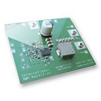
IRDC3812
Description
BOARD EVAL SYNC BUCK CONVERTER
Manufacturer
International Rectifier
Specifications of IRDC3812
Silicon Manufacturer
International Rectifier
Kit Application Type
Power Management - Voltage Regulator
Application Sub Type
Synchronous Buck Converter
Features
Programmable Soft Start, Programmable
Rohs Compliant
Yes


LAYOUT
The PCB is a 4-layer board. All of layers are 2 Oz. copper. The IR3812 SupIRBuck and all of the
passive components are mounted on the top side of the board.
Power supply decoupling capacitors, the charge-pump capacitor and feedback components are located
close to IR3812. The feedback resistors are connected to the output voltage at the point of regulation
and are located close to the SupIRBuck.
To improve efficiency, the circuit board is designed to minimize the length of the on-board power ground
current path.
CONNECTIONS and OPERATING INSTRUCTIONS
A well regulated +12V input supply should be connected to VIN+ and VIN-. A maximum 4A load should be
connected to VOUT+ and VOUT-. The connection diagram is shown in Fig. 1 and inputs and outputs of the
board are listed in Table I.
IR3812 has two input supplies, one for biasing (Vcc) and the other as input voltage (Vin). These inputs are
connected on the board with a zero ohm resistor (R15).
removed.
Vp pin is connected to the internal reference (Vref) via R14 as the default configuration. External input can
be applied to Vp.
external tracking source should be applied between Vp_Ext and Agnd.
selected to provide the desired ratio between the output voltage and the tracking input. For proper operation
of IR3811, the voltage at Vp pin should be kept between 0.2V to 1.0V.
Rev 0.1
01/07/2008
Vcc input should be a well regulated 5V-12V supply and it would be connected to Vcc+ and Vcc-.
For tacking applications, R14 should be removed, R17 should be inserted, and the
Connection
VIN+
VIN-
Vcc+
Vcc-
VOUT-
VOUT+
Vp_Ext
Agnd
Table I. Connections
Signal Name
V
Ground of V
Optional Vcc input
Ground for optional Vcc input
Ground of V
V
Optional Tracking input
Analog (Signal) Ground
in
out
(+12V)
(+1.8V)
in
out
Vcc input cannot be connected unless R15 is
The value of R17 and R28 can be
IRDC3812
2
Related parts for IRDC3812
Image
Part Number
Description
Manufacturer
Datasheet
Request
R

Part Number:
Description:
SCHOTTKY RECTIFIER
Manufacturer:
International Rectifier Corp.
Datasheet:
Part Number:
Description:
SCHOTTKY RECTIFIER
Manufacturer:
International Rectifier Corp.
Datasheet:
Part Number:
Description:
SCHOTTKY RECTIFIER
Manufacturer:
International Rectifier Corp.
Datasheet:
Part Number:
Description:
SCHOTTKY RECTIFIER
Manufacturer:
International Rectifier Corp.
Datasheet:
Part Number:
Description:
SCHOTTKY RECTIFIER
Manufacturer:
International Rectifier Corp.
Datasheet:
Part Number:
Description:
SCHOTTKY RECTIFIER
Manufacturer:
International Rectifier Corp.
Datasheet:
Part Number:
Description:
SCHOTTKY RECTIFIER
Manufacturer:
International Rectifier Corp.
Datasheet:
Part Number:
Description:
SCHOTTKY RECTIFIER
Manufacturer:
International Rectifier Corp.
Datasheet:
Part Number:
Description:
SCHOTTKY RECTIFIER
Manufacturer:
International Rectifier Corp.
Datasheet:
Part Number:
Description:
SCHOTTKY RECTIFIER
Manufacturer:
International Rectifier Corp.
Datasheet:
Part Number:
Description:
SCHOTTKY RECTIFIER
Manufacturer:
International Rectifier Corp.
Datasheet:
Part Number:
Description:
SCHOTTKY RECTIFIER
Manufacturer:
International Rectifier Corp.
Datasheet:
Part Number:
Description:
SCHOTTKY RECTIFIER
Manufacturer:
International Rectifier Corp.
Datasheet:
Part Number:
Description:
SCHOTTKY RECTIFIER
Manufacturer:
International Rectifier Corp.
Datasheet:
Part Number:
Description:
SCHOTTKY RECTIFIER
Manufacturer:
International Rectifier Corp.
Datasheet: