DAK-71A Power Integrations, DAK-71A Datasheet - Page 11
DAK-71A
Manufacturer Part Number
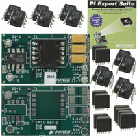
DAK-71A
Description
KIT DESIGN ACCELERATOR DC-DC
Manufacturer
Power Integrations
Series
DPA-Switch®r
Specifications of DAK-71A
Main Purpose
DC/DC, Step Down
Outputs And Type
1, Isolated
Voltage - Output
3.3V
Current - Output
2A
Voltage - Input
36 ~ 72V
Regulator Topology
Flyback
Frequency - Switching
400kHz
Board Type
Bare (Unpopulated) and Fully Populated
Utilized Ic / Part
DPA423, DPA424, DPA425
Lead Free Status / RoHS Status
Not applicable / Not applicable
Power - Output
-
Lead Free Status / Rohs Status
Lead free / RoHS Compliant
Other names
596-1009


Typical Uses of FREQUENCY (F) Pin
Typical Uses of LINE-SENSE (L) and EXTERNAL CURRENT LIMIT (X) Pins
Figure 11. Three Terminal Operation (LINE-SENSE and EXTERNAL CURRENT
Figure 13. Line-Sensing for Under-Voltage Only (Overvoltage Disabled).
Figure 9.
www.powerint.com
Voltage
Voltage
Input
Voltage
Input
DC
Input
DC
LIMIT Features Disabled. FREQUENCY Pin can be tied to SOURCE or
CONTROL Pin).
400 kHz Frequency Operation.
+
DC
+
-
+
-
-
15 V
D
S
D
S
D
S
CONTROL
CONTROL
CONTROL
L
X
464 kΩ
1%
150 kΩ
1%
L
F
F
C
C
C
R
LS
V
For Values Shown
UV
V
UV
C
C L X S F
= R
= 33.1 V
V
PI-2852-121504
S
PI-2766-070901
LS
L (I
PI-2654-071700
L
x I
= I
UV
D
D
UV
)
+
Figure 12. Line-Sensing for Under-Voltage, Overvoltage and Line Feed-forward.
Figure 10. 300 kHz Frequency Operation.
Figure 14. Line-Sensing for Overvoltage Only (Under-Voltage Disabled).
Voltage
Voltage
Voltage
Input
Input
Input
DC
DC
DC
Maximum Duty Cycle will be reduced at Low Line.
+
+
+
-
-
-
D
S
R
D
S
D
S
LS
CONTROL
R
CONTROL
CONTROL
LS
L
L
619 kΩ
1%
590 kΩ
1%
30 kΩ
1%
DPA422-426
V
V
F
UV
OV
= I
= I
C
C
C
UV
OV
x R
For R
x R
1N4148
V
V
V
For Values Shown
UV
OV
LS
LS
OV
V
OV
LS
+ V
+ V
= 33.3 V
= 86.0 V
= I
= 619 k
= 86.2 V
V
OV
L (I
PI-2655-071700
L (I
PI-2767-091302
L (I
PI-2853-091302
L
L
x R
L
= I
= I
= I
Rev. S 12/07
UV
OV
LS
Ω
OV
)
)
11
+
)
Related parts for DAK-71A
Image
Part Number
Description
Manufacturer
Datasheet
Request
R

Part Number:
Description:
KIT DESIGN ACCELERATOR APPLIANCE
Manufacturer:
Power Integrations
Datasheet:

Part Number:
Description:
KIT DESIGN ACCELERATOR MODEM
Manufacturer:
Power Integrations
Datasheet:

Part Number:
Description:
KIT DESIGN ACCELERATOR SET TOP
Manufacturer:
Power Integrations
Datasheet:

Part Number:
Description:
KIT REF DES DPA 6.6W DC-DC CONV
Manufacturer:
Power Integrations
Datasheet:

Part Number:
Description:
KIT DESIGN ACCELERATOR POE CONV
Manufacturer:
Power Integrations
Datasheet:

Part Number:
Description:
DESIGN ACCELERATOR KIT XT SWITCH
Manufacturer:
Power Integrations
Datasheet:

Part Number:
Description:
DESIGN ACCELERATOR KIT LP SWITCH
Manufacturer:
Power Integrations
Datasheet:

Part Number:
Description:
KIT DESIGN ACC PEAKSWITCH FAMILY
Manufacturer:
Power Integrations
Datasheet:

Part Number:
Description:
KIT DESIGN ACCELERATOR ADAPTER
Manufacturer:
Power Integrations
Datasheet:

Part Number:
Description:
KIT DESIGN ACCELERATOR ADAPTER
Manufacturer:
Power Integrations
Datasheet: