MCP1602EV Microchip Technology, MCP1602EV Datasheet - Page 4
MCP1602EV
Manufacturer Part Number
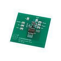
MCP1602EV
Description
BOARD EVALUATION FOR MCP1602
Manufacturer
Microchip Technology
Type
DC/DC Switching Converters, Regulators & Controllersr
Specifications of MCP1602EV
Main Purpose
DC/DC, Step Down
Outputs And Type
1, Non-Isolated
Voltage - Output
0.8V, 1.2V, 1.8V, 2.5V, or 3.3V
Current - Output
500mA
Voltage - Input
2.7 ~ 5.5V
Regulator Topology
Buck
Frequency - Switching
2MHz
Board Type
Fully Populated
Utilized Ic / Part
MCP1602
Input Voltage
2.7 V to 5.5 V
Output Voltage
0.8 V to 3.3 V
Product
Power Management Modules
For Use With/related Products
MCP1602
Lead Free Status / RoHS Status
Lead free / RoHS Compliant
Power - Output
-
Lead Free Status / Rohs Status
Lead free / RoHS Compliant
Available stocks
Company
Part Number
Manufacturer
Quantity
Price

Part Number:
MCP1602EV
Manufacturer:
MICROCHIP/微芯
Quantity:
20 000


MCP1602
1.0
Absolute Maximum Ratings †
V
All Other I/O .............................. (A
LX to P
Output Short Circuit Current..................................Continuous
Power Dissipation (Note 6) ..........................Internally Limited
Storage Temperature.................................... -65
Ambient Temp. with Power Applied................ -40
Operating Junction Temperature.................. -40
ESD Protection On All Pins:
DC CHARACTERISTICS
DS22061A-page 4
Electrical Characteristics: Unless otherwise indicated, V
V
Input Characteristics
Input Voltage
Maximum Output Current
Shutdown Current
Quiescent Current
Shutdown/UVLO/Thermal Shutdown Characteristics
SHDN, Logic Input Voltage Low
SHDN, Logic Input Voltage High
SHDN, Input Leakage Current
Undervoltage Lockout
Undervoltage Lockout Hystere-
Thermal Shutdown
Thermal Shutdown Hysteresis
Output Characteristics
Adjustable Output Voltage
Range
Reference Feedback Voltage
Feedback Input Bias Current
Note 1:
IN
HBM..............................................................................3 kV
MM...............................................................................200V
OUT
sis
- A
GND
(ADJ) = 1.8V, I
GND
2:
3:
4:
5:
6:
7:
ELECTRICAL
CHARACTERISTICS
......................................................................+6.0V
............................................. -0.3V to (V
Parameters
The minimum V
Reference Feedback Voltage Tolerance applies to adjustable output voltage setting.
V
Regulation is measured at a constant junction temperature using low duty cycle pulse testing. Load
regulation is tested over a load range of 0.1 mA to the maximum specified output current. Changes in
output voltage due to heating effects are covered by the thermal regulation specification.
The maximum allowable power dissipation is a function of ambient temperature, the maximum allowable
temperature and the thermal resistance from junction to air (i.e. T
allowable power dissipation causes the device to initiate thermal shutdown.
The internal MOSFET switches have an integral diode from the L
to the GND pin. In cases where these diodes are forward-biased, the package power dissipation limits
must be adhered too. Thermal protection is not able to limit the junction temperature for these cases.
The current limit threshold is a cycle-by-cycle current limit.
R
is the output voltage setting.
OUT
= 100 mA, T
IN
has to meet two conditions: V
GND
UVLO
- 0.3V) to (V
T
V
I
IN_SHDN
SHD-HYS
UVLO
L_SHND
V
T
Sym
I
I
V
V
OUT
V
A
V
VFB
SHD
OUT
I
Q
FB
IN
IH
IL
= +25°C. Boldface specifications apply for the T
HYS
o
o
C to +150
C to +125
o
C to +85
IN
IN
2.40
Min
-1.0
+ 0.3V)
+ 0.3V)
500
2.7
0.8
—
—
—
45
—
—
—
—
—
o
o
o
C
C
C
0.05
±0.1
2.55
Typ
200
150
-1.5
0.8
45
10
—
—
—
—
—
IN
IN
= 3.6V, C
≥ 2.7V and V
† Notice: Stresses above those listed under "Maximum
Ratings" may cause permanent damage to the device. This is
a stress rating only and functional operation of the device at
those or any other conditions above those indicated in the
operational sections of this specification is not intended.
Exposure to maximum rating conditions for extended periods
may affect device reliability.
Max
2.70
5.5
1.0
4.5
—
60
15
—
—
—
—
—
—
1
OUT
Units
%V
%V
mA
mV
µA
µA
µA
°C
°C
nA
V
V
V
V
IN
= C
IN
IN
A
X
≥ V
, T
pin to the V
IN
J
OUT
= 4.7 µF, L = 4.7 µH,
Note 1
Note 1
SHDN = GND
SHDN = V
V
V
V
V
Note 5, Note 6
Note 5, Note 6
Note 2
, θ
IN
IN
IN
IN
JA
= 2.7V to 5.5V
= 2.7V to 5.5V
= 2.7V to 5.5V, SHDN = A
Falling
+ 0.5V.
). Exceeding the maximum
© 2007 Microchip Technology Inc.
A
IN
range of -40
IN
pin, and from the L
Conditions
, I
OUT
= 0 mA
o
C to +85
GND
X
o
pin
C.
Related parts for MCP1602EV
Image
Part Number
Description
Manufacturer
Datasheet
Request
R

Part Number:
Description:
Manufacturer:
Microchip Technology Inc.
Datasheet:
Part Number:
Description:
Manufacturer:
Microchip Technology Inc.
Datasheet:
Part Number:
Description:
Manufacturer:
Microchip Technology Inc.
Datasheet:
Part Number:
Description:
Manufacturer:
Microchip Technology Inc.
Datasheet:
Part Number:
Description:
Manufacturer:
Microchip Technology Inc.
Datasheet:
Part Number:
Description:
Manufacturer:
Microchip Technology Inc.
Datasheet:
Part Number:
Description:
Manufacturer:
Microchip Technology Inc.
Datasheet:
Part Number:
Description:
Manufacturer:
Microchip Technology Inc.
Datasheet: