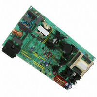
NCP1605FORWGEVB ON Semiconductor, NCP1605FORWGEVB Datasheet - Page 14

NCP1605FORWGEVB
Manufacturer Part Number
NCP1605FORWGEVB
Description
EVAL BOARD FOR NCP1605FORWG
Manufacturer
ON Semiconductor
Datasheets
1.NCP1217P100G.pdf
(19 pages)
2.NCP1605ADR2G.pdf
(32 pages)
3.NCP1605FORWGEVB.pdf
(2 pages)
4.NCP1605FORWGEVB.pdf
(20 pages)
Specifications of NCP1605FORWGEVB
Design Resources
NCP1605FORWGEVB BOM NCP1605FORWGEVB Gerber Files NCP1605 EVB Schematic
Main Purpose
AC/DC, Primary and Secondary Side with PFC
Outputs And Type
1, Isolated
Voltage - Output
19V
Current - Output
8A
Voltage - Input
90 ~ 265VAC
Regulator Topology
Forward Converter
Frequency - Switching
133kHz
Board Type
Fully Populated
Utilized Ic / Part
NCP1217, NCP1605
Lead Free Status / RoHS Status
Lead free / RoHS Compliant
Power - Output
-
Lead Free Status / Rohs Status
Lead free / RoHS Compliant
For Use With/related Products
NCP1605FORWG
Other names
NCP1605FORWGEVBOS
Protection of the PFC Stages
rugged PFC stages:
•
•
•
•
The NCP1605 protection features allow the design of very
The following brownout detection levels were
measured (the 19 V output being loaded by a 5 A
current):
As shown by Figure 14, the line current is limited to
3.2 A. This corresponds to proper expected level with
R
Pin 14 monitors a portion of the output voltage and
stops the circuit switching as long as the pin14 voltage
exceeds 2.5 V. This overvoltage protection (OVP)
guarantees that the bulk voltage cannot exceed the set
OVP level (about 410 V here).
The undervoltage that is also attached to pin 14, detects
if the OVP pin is accidentally grounded or if one of the
upper resistors is not correctly connected and prevents
the circuit operation in case of such a fault. Ultimately,
OCP
- Minimum line RMS voltage to start operation:
83 V.
- RMS line voltage being which the system stops
operation: 74 V.
I
= 2.4 kW:
LINE,MAX
+
R
2 @ R
OCP
(This Test was Made by Creating an Overload Condition at 90 Vrms).
SENSE
@ I
REF
+
Figure 14. Action of the Overcurrent Limitation
2.4 k @ 250 mA
2 @ 0.1
http://onsemi.com
+ 3 A
AND8292
14
•
biased.
which is closed to
if R42 is small compared to R11 and if D3 is properly
this protection avoids the power supply destruction if
there is a failure in the OVP sensing network.
Shut-down: if more than 2.5 V are applied to pin 13,
the circuit latches off and cannot recover operation until
the SMPS is unplugged (to enable the NCP1605 V
voltage to drop below its 4 V reset voltage). This
latchoff capability is supposed to trigger in case of a
major fault like any overheating of the SMPS. In this
application, it is used to disable the power supply in
case of a severe runaway of the V
simply made by applying the V
16 V zener diode (D3) so that if (V
2.5 V, the circuit latches off (see Figure 2). R11 adjusts
the biasing current through D3 and together with R42
and C5, this resistor avoids that the protection falsely
triggers due to some noise. R42 is chosen small
compared to R11 not to modify the threshold since the
actual voltage applied to pin 13 is:
AC Line Current (2 A/div)
R11 ) R42
(V
CC
R11
* 16 V)
V
BULK
VI
N
@ (V
(100 V/div)
(100 V/div)
CC
* V
D3
),
CC
CC
voltage through a
CC
voltage. This is
-16 V) exceeds
CC


