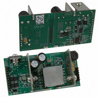
NCP1083WIRGEVB ON Semiconductor, NCP1083WIRGEVB Datasheet
NCP1083WIRGEVB
Specifications of NCP1083WIRGEVB


Related parts for NCP1083WIRGEVB

NCP1083WIRGEVB Summary of contents
Page 1
... Converter Controller with 9 V Auxiliary Supply Support Introduction The NCP1083 is a member of ON Semiconductor’s high power HIPOt Power over Ethernet Powered Device (PoE−PD) product family and represents a robust, flexible and highly integrated solution targeting demanding medium and high power Ethernet applications. It combines in a single unit an enhanced PoE− ...
Page 2
DC−DC Converter Controller • Current Mode Control • Supports Isolated and Non−isolated DC−DC Converter Applications • Internal Voltage Regulators • Wide Duty Cycle Range with Internal Slope Compensation Circuitry • Programmable Oscillator Frequency • Programmable Soft−start Time Ordering Information Part ...
Page 3
VAUX(+) D3 RJ−45 DB1 Data Pairs Raux1 Raux2 D2 DB2 Raux3 Spare Pairs Z_line VAUX(−) Figure 2. Isolated Fly−back Converter with Rear Auxiliary Supply Figure 2 shows the integrated PoE−PD switch and DC−DC controller configured to work in a fully ...
Page 4
VAUX(+) D4 RJ−45 DB1 Data Pairs Raux1 Raux2 D3 DB2 Raux3 Spare Pairs Z_line VAUX(−) Figure 4. Non−Isolated Fly−back with Extra Winding and Rear Auxiliary Supply Figure 4 shows the same non−isolated fly−back configuration as Figure 3, but adds a ...
Page 5
Table 1. Pin Descriptions Name Pin No. Type VPORTP 1 Supply VPORTN1 6,8 Ground VPORTN2 RTN 7 Ground ARTN 14 Ground VDDH 16 Supply VDDL 17 Supply CLASS 2 Input INRUSH 4 Input ILIM1 5 Input UVLO 3 Input GATE ...
Page 6
Table 2. Absolute Maximum Ratings Symbol Parameter VPORTP Input power supply RTN Analog ground supply 2 ARTN VDDH Internal regulator output VDDL Internal regulator output CLASS Analog output INRUSH Analog output ILIM1 Analog output UVLO Analog input OSC Analog output ...
Page 7
Recommended Operating Conditions Operating conditions define the limits for functional operation and parametric characteristics of the device. Note that the functionality of the device outside the operating conditions described in this section is not warranted. Operating outside the recommended operating ...
Page 8
Table 3. Operating Conditions Symbol Parameter UVLO Vuvlo_on Default turn on voltage (VportP rising) Vuvlo_off Default turn off voltage (VportP falling) Vhyst_int UVLO internal hysteresis Vuvlo_pr UVLO external programming range Vuvlo_pr_aux UVLO external programming VPORT range with auxiliary supply support ...
Page 9
Table 3. Operating Conditions Symbol Parameter PASS−SWITCH AND CURRENT LIMITS Ron Pass−switch Rds−on I_Rinrush1 Rinrush = 150 kW (Note 11) I_Rinrush2 Rinrush = 57.6 kW (Note 11) I_Rilim1 Rilim1 = 84.5 kW (Note 11) I_Rilim2 Rilim1 = 66.5 kW (Note ...
Page 10
Table 3. Operating Conditions Symbol Parameter SOFT−START Vss Soft−start voltage range Vss_r Soft−start low threshold (rising edge) Iss Soft−start source current CURRENT LIMIT COMPARATOR CSth CS threshold voltage Tblank Blanking time OSCILLATOR DutyC Maximum duty cycle Frange Oscillator frequency range ...
Page 11
Powered Device Interface The PD interface portion of the NCP1083 supports the IEEE 802.3af and draft IEEE 802.3at (D3.0) defined operating modes: detection signature, current source classification, inrush and operating current limits. In order to give more flexibility to the ...
Page 12
V Class range 13 V 9.7 V Mark Range 5.4 V Reset Range 0 V Operation Mode: Detection Number of Mark Event: X PSE Type identification: Figure 9. Hardware Physical Classification Event Sequence nCLASS_AT Indicator The nCLASS_AT active low ...
Page 13
The PSE performed a one event hardware classification (it can be a IEEE 802.3af or a draft IEEE 802.3at (D3.0) compliant PSE with Layer 2 engine). • The PSE performed a two event hardware classification but it did not ...
Page 14
When the auxiliary input supply is above 13.5 V, connect the AUX pin to VPORTN . When the auxiliary supply is 1,2 below 13.5 V (but above 9 V), calculate the voltage dividers Raux1, Raux3 and Raux2, Rdet1, Rdet2 to ...
Page 15
When VPORT reaches the UVLO_on level, the Cpd capacitor is charged with the INRUSH current (in order to limit the internal power dissipation of the pass−switch). Once the Cpd capacitor is fully charged, the current limit switches from the inrush ...
Page 16
Both VDDH and VDDL regulators turn on as soon as VPORT reaches the Vuvlo_on threshold. Error Amplifier In non−isolated converter topologies, the high gain internal error amplifier of the NCP1083 and the internal 1.2 V reference voltage regulate the DC−DC ...
Page 17
... P P1 BOTTOM VIEW *For additional information on our Pb−Free strategy and soldering details, please download the ON Semiconductor Soldering and Mounting Techniques Reference Manual, SOLDERRM/D. The product described herein may be covered by one or more US patents pending. ON Semiconductor and are registered trademarks of Semiconductor Components Industries, LLC (SCILLC). SCILLC reserves the right to make changes without further notice to any products herein ...