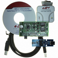
MULTIPHSPOL-RD Silicon Laboratories Inc, MULTIPHSPOL-RD Datasheet - Page 10

MULTIPHSPOL-RD
Manufacturer Part Number
MULTIPHSPOL-RD
Description
KIT REFERENCE DESIGN FOR SI825X
Manufacturer
Silicon Laboratories Inc
Type
Other Power Managementr
Specifications of MULTIPHSPOL-RD
Main Purpose
DC/DC, Step Down
Outputs And Type
1, Non-Isolated
Voltage - Output
3.3V
Current - Output
40A
Voltage - Input
10 ~ 15V
Regulator Topology
Buck
Frequency - Switching
391kHz
Board Type
Fully Populated
Utilized Ic / Part
SI8250, SI8251, SI8252
Input Voltage
10 V to 15 V
Output Voltage
3.3 V
Interface Type
USB
Product
Power Management Modules
Supply Current
10 A
For Use With/related Products
Si8250
Lead Free Status / RoHS Status
Contains lead / RoHS non-compliant
Power - Output
-
Lead Free Status / Rohs Status
Lead free / RoHS Compliant
Other names
336-1323
Si825x Multi-Phase POL-RD
7.3. Evaluation C51 C Compiler
An evaluation version of the Keil C51 C compiler is included with the development kit and is installed during IDE
installation. The evaluation version of the C51 compiler is the same as the full professional version except, that
code size is limited to 4 kB, and the floating point library is not included. The C51 compiler reference manual can
be found under the Help menu in the IDE or in the “SiLabs\MCU\hlp” directory (C51.pdf).
7.4. Using the Keil Software 8051 Tools with the Silicon Laboratories IDE
To perform source-level debugging with the IDE, you must configure the Keil 8051 tools to generate an absolute
object file in the OMF-51 format with object extensions and debug records enabled. You may build the OMF-51
absolute object file by calling the Keil 8051 tools at the command line (e.g. batch file or make file) or by using the
project manager built into the IDE. The default configuration when using the Silicon Laboratories IDE project
manager enables object extension and debug record generation. Refer to application note “AN104: Integrating Keil
8051 Tools Into the Silicon Labs IDE” for additional information on using the Keil 8051 tools with the Silicon
Laboratories IDE.
To build an absolute object file using the Silicon Laboratories IDE project manager, you must first create a project.
A project consists of a set of files, IDE configuration, debug views, and a target build configuration (list of files and
tool configurations used as input to the assembler, compiler, and linker when building an output object file).
The following sections illustrate the steps necessary to manually create a project with one or more source files,
build a program, and download the program to the target in preparation for debugging. (The IDE will automatically
create a single-file project using the currently open and active source file if you select “Build/Make Project” before a
project is defined.)
7.4.1. Creating a New Project
1. Select Project→New Project to open a new project and reset all configuration settings to default.
2. Select File→New File to open an editor window. Create your source file(s) and save the file(s) with a
3. Right-click on New Project in the Project Window. Select Add files to project. Select files in the file browser
4. For each of the files in the Project Window that you want assembled, compiled, and linked into the target build,
7.4.2. Building and Downloading the Program for Debugging
1. Once all source files have been added to the target build, build the project by clicking on the “Build/Make
2. Before connecting to the target device, several connection options may need to be set. Open the “Connection
3. Click the Connect button in the toolbar or select Debug→Connect from the menu to connect to the device.
4. Download the project to the target by clicking the Download Code button in the toolbar.
10
recognized extension, such as *.c, *.h, or *.asm, to enable color syntax highlighting.
and click “Open”. Continue adding files until all project files have been added.
right-click on the file name and select Add file to build. Each file will be assembled or compiled as appropriate
(based on file extension) and linked into the build of the absolute object file.
Note: If a project contains a large number of files, the “Group” feature of the IDE can be used to organize them. Right-click
Project” button in the toolbar or selecting Project→Build/Make Project from the menu.
Note: After the project has been built the first time, the Build/Make Project command will only build the files that have been
Options” window by selecting Options→Connection Options... in the IDE menu. First, select the adapter that
was included with the kit in the “Serial Adapter” section. Next, the correct “Debug Interface” must be selected.
Si825x family devices use the Silicon Laboratories 2-wire (C2) debug interface. Once all the selections are
made, click the OK button to close the window.
Note: To enable automatic downloading if the program build is successful, select Enable automatic connect/download
on New Project in the Project Window. Select Add Groups to project. Add predefined groups or add customized
groups. Right-click on the group name and choose Add file to group. Select files to be added. Continue adding files
until all project files have been added.
changed since the previous build. To rebuild all files and project dependencies, click on the “Rebuild All” button in the
toolbar or select Project->Rebuild All from the menu.
after build in the Project→Target Build Configuration dialog. If errors occur during the build process, the IDE will
not attempt the download.
Confidential Rev. 0.2


