LM5020EVAL National Semiconductor, LM5020EVAL Datasheet - Page 2
LM5020EVAL
Manufacturer Part Number
LM5020EVAL
Description
EVALUATION BOARD FOR LM5020
Manufacturer
National Semiconductor
Series
PowerWise®r
Specifications of LM5020EVAL
Main Purpose
DC/DC, Step Down
Outputs And Type
1, Isolated
Voltage - Output
3.3V
Current - Output
4.5A
Voltage - Input
30 ~ 75V
Regulator Topology
Buck
Board Type
Fully Populated
Utilized Ic / Part
LM5020
Lead Free Status / RoHS Status
Contains lead / RoHS non-compliant
Power - Output
-
Frequency - Switching
-
Other names
*LM5020EVAL


www.national.com
Powering and Loading
Considerations
When applying power to the LM5020 evaluation board cer-
tain precautions should be followed. The LM5020 evaluation
board is quite forgiving of load and input power variations.
The possibility of shipping damage or infant failure is always
a concern at first power-up.
Proper Connections
Be sure to choose the correct wire size when attaching the
source supply and the load. Monitor the current into and out
of the UUT. Monitor the voltages in and out directly at the
terminals of the UUT. The voltage drop across the connect-
ing wires will yield inaccurate measurements. For accurate
efficiency measurements, these precautions are especially
important.
Source Power
At low input line voltage (30V) the input current will be
approximately 0.63A, while at high input line voltage the
input current will be approximately 0.23. Therefore to fully
test the LM5020 evaluation board a DC power supply ca-
pable of at least 75V and 1A is required. The power supply
must have adjustments for both voltage and current. An
accurate readout of output current is desirable since the
current is not subject to loss in the cables as voltage is.
The power supply and cabling must present a low imped-
ance to the UUT. Insufficient cabling or a high impedance
power supply will cause droop during power supply applica-
tion with the UUT inrush current. If large enough, this droop
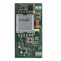
Typical Evaluation Setup
2
will cause a chattering condition upon power up. This chat-
tering condition is an interaction with the UUT undervoltage
lockout, the cabling impedance and the inrush current.
Loading
An appropriate electronic load specified for operation down
to 2.0V is desirable. The maximum load current is specified
as 4.5A. Minimum load is specified at 5% or 0.23A. The
resistance of a maximum load is 0.73Ω (including cables).
The resistance of a minimum load is 14.4Ω.
Powering Up
Using the shutdown feature provided on the UUT will allow
powering up the source supply initially with a low current
level. It is suggested that the load be kept reasonably low
during the first power up. Set the current limit of the source
supply to provide about 1
you remove the connection from the shutdown pin to ground,
immediately check for 3.3 volts at the output. If more than a
couple of seconds pass without seeing an output voltage,
remove input power.
A quick efficiency check is the best way to confirm that the
UUT is operating properly. If something is amiss you can be
reasonably sure that it will affect the efficiency adversely.
Few parameters can be incorrect in a switching power sup-
ply without creating additional losses and potentially damag-
ing heat. An efficiency above 80% is expected.
After the unit is verified operationally, it can be powered up
without use of the shutdown pin.
1
⁄
2
times the wattage of the load. As
20095302
Related parts for LM5020EVAL
Image
Part Number
Description
Manufacturer
Datasheet
Request
R

Part Number:
Description:
National Semiconductor [8-Bit D/A Converter]
Manufacturer:
National Semiconductor
Datasheet:
Part Number:
Description:
National Semiconductor [Media Coprocessor]
Manufacturer:
National Semiconductor
Datasheet:
Part Number:
Description:
Digitally Controlled Tone and Volume Circuit with Stereo Audio Power Amplifier, Microphone Preamp Stage and National 3D Sound
Manufacturer:
National Semiconductor
Datasheet:
Part Number:
Description:
Digitally Controlled Tone and Volume Circuit with Stereo Audio Power Amplifier, Microphone Preamp Stage and National 3D Sound
Manufacturer:
National Semiconductor
Datasheet:
Part Number:
Description:
AC97 Rev 2 Codec with Sample Rate Conversion and National 3D Sound
Manufacturer:
National Semiconductor
Part Number:
Description:
Manufacturer:
National Semiconductor
Datasheet:
Part Number:
Description:
Manufacturer:
National Semiconductor
Datasheet:
Part Number:
Description:
General Purpose, Low Voltage, Low Power, Rail-to-Rail Output Operational Amplifiers
Manufacturer:
National Semiconductor
Datasheet:
Part Number:
Description:
8-bit 20 MSPS flash A/D converter.
Manufacturer:
National Semiconductor
Datasheet:
Part Number:
Description:
Low Noise Quad Operational Amplifier
Manufacturer:
National Semiconductor
Datasheet:
Part Number:
Description:
Quad Differential Line Receivers
Manufacturer:
National Semiconductor
Datasheet:
Part Number:
Description:
Quad High Speed Trapezoidal? Bus Transceiver
Manufacturer:
National Semiconductor
Datasheet:
Part Number:
Description:
Dual Line Receiver
Manufacturer:
National Semiconductor
Datasheet:
Part Number:
Description:
TTL to 10k ECL Level Translator with Latch
Manufacturer:
National Semiconductor
Datasheet: