SSM2317-MINI-EVALZ Analog Devices Inc, SSM2317-MINI-EVALZ Datasheet - Page 15
SSM2317-MINI-EVALZ
Manufacturer Part Number
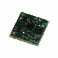
SSM2317-MINI-EVALZ
Description
BOARD EVAL MINI SSM2317
Manufacturer
Analog Devices Inc
Specifications of SSM2317-MINI-EVALZ
Amplifier Type
Class D
Output Type
1-Channel (Mono)
Max Output Power X Channels @ Load
3.89W x 1 @ 3 Ohm
Voltage - Supply
2.5 V ~ 5.5 V
Operating Temperature
-40°C ~ 85°C
Board Type
Fully Populated
Utilized Ic / Part
SSM2317
Silicon Manufacturer
Analog Devices
Application Sub Type
Audio Power Amplifier - Class D
Kit Application Type
Amplifier
Silicon Core Number
SSM2317
Kit Contents
Board
Lead Free Status / RoHS Status
Lead free / RoHS Compliant


compared with double-sided boards. A multilayer board allows
a complete layer to be used for the ground plane, whereas the
ground plane side of a double-sided board is often disrupted with
signal crossover.
If the system has separate analog and digital ground and power
planes, place the analog ground plane underneath the analog power
plane, and, similarly, place the digital ground plane underneath the
digital power plane. There should be no overlap between analog
and digital ground planes or analog and digital power planes.
INPUT CAPACITOR SELECTION
The SSM2317 does not require input coupling capacitors if
the input signal is biased from 1.0 V to V
capacitors are required if the input signal is not biased within
this recommended input dc common-mode voltage range, if
high-pass filtering is needed, or if a single-ended source is used.
If high-pass filtering is needed at the input, the input capacitor
and the input resistor of the SSM2317 form a high-pass filter
whose corner frequency is determined by the following
equation:
The input capacitor can significantly affect the performance of
the circuit. Not using input capacitors degrades both the output
offset of the amplifier and the dc PSRR performance.
PROPER POWER SUPPLY DECOUPLING
To ensure high efficiency, low total harmonic distortion (THD),
and high PSRR, proper power supply decoupling is necessary.
Noise transients on the power supply lines are short-duration
voltage spikes. Although the actual switching frequency can
range from 10 kHz to 100 kHz, these spikes can contain frequency
components that extend into the hundreds of megahertz. The
power supply input needs to be decoupled with a good quality
low ESL, low ESR capacitor, usually of around 4.7 μF. This
capacitor bypasses low frequency noises to the ground plane.
For high frequency transient noises, use a 0.1 μF capacitor as
close as possible to the VDD pin of the device. Placing the
decoupling capacitor as close as possible to the SSM2317 helps
maintain efficient performance.
AUTOMATIC LEVEL CONTROL (ALC)
Automatic level control (ALC) is a function that automatically
adjusts amplifier gain to generate desired output amplitude with
reference to a particular input stimulus. The primary motivation
for the use of ALC is to protect an audio power amplifier or
speaker load from the damaging effects of clipping or current
overloading. This is accomplished by limiting the amplifier’s
output amplitude upon reaching a preset threshold voltage. A
less intuitive benefit of ALC is that it makes sound sources with
a wide dynamic range more intelligible by boosting low level
signals yet limits very high level signals.
Figure 42 shows input vs. output and gain characteristics of
ALC that is implemented in the SSM2317.
f
C
= 1/{2π × (10 kΩ + R
EXT
) × C
IN
}
DD
− 1.0 V. Input
Rev. A | Page 15 of 20
When the input level is small and below the ALC threshold
value, the gain of the amplifier stays at 18 dB. When the input
exceeds the ALC threshold value, the ALC begins to gradually
reduce the gain from 18 dB to 3.5 dB.
OPERATING MODES
The ALC implemented on SSM2317 has two operating modes:
compression and limiting. At the time the ALC is triggered for
medium level input, the ALC is in compression mode. In this
mode, an increase of the output signal is 1/3 of the increase of
the input signal. For example, if the input signal increases by
3 dB, the ALC reduces the amplifier gain by 2 dB and thus the
output signal only increases by 1 dB.
As the input signal becomes very large, the ALC transitions into
limiting operation mode. In this mode, the output stays at a
given threshold level, V
For example, when a large input signal increases by 3 dB, the
ALC reduces the amplifier gain by 3 dB and thus the output
increases 0 dB. When the amplifier gain is reduced to 3.5 dB,
ALC cannot further reduce the gain and the output increases
again. To avoid potential speaker damage, the maximum input
signal should not be large enough to exceed the maximum
attenuation (3.5 dB) of the limiting operational mode.
ATTACK TIME, HOLD TIME, AND RELEASE TIME
When the amplifier input exceeds a preset threshold, ALC
reduces amplifier gain rapidly until its output settles to a target
level. This gain level is maintained for a certain period. If the
input does not exceed the threshold again, ALC increases the
gain gradually. The attack time is the time taken to reduce the
gain from maximum to minimum. The hold time is the time to
sustain the reduced gain. The release time is the time taken to
increase the gain from minimum to maximum. These times are
shown in Table 5.
Table 5. Attack, Hold, and Release Times
Time
Attack Time
Hold Time
Release Time
24
21
18
15
12
9
6
3
0
–30
Figure 42. Input/Output Characteristic and Gain
GAIN
–20
TH
, even if the input signal grows larger.
INPUT (dBV)
–10
OUTPUT
Duration (ms)
0.1
35
550
0
SSM2317
10
12
9
6
3
0
–3
–6
–9
–12
Related parts for SSM2317-MINI-EVALZ
Image
Part Number
Description
Manufacturer
Datasheet
Request
R

Part Number:
Description:
BOARD EVAL SSM2317
Manufacturer:
Analog Devices Inc
Datasheet:

Part Number:
Description:
Filterless High Efficiency Mono 3 W Class-d Audio Amplifier
Manufacturer:
Analog Devices, Inc.
Datasheet:

Part Number:
Description:
±1.7g Dual-Axis IMEMS Accelerometer Evaluation Board
Manufacturer:
Analog Devices Inc
Datasheet:

Part Number:
Description:
Inertial Sensor Evaluation System
Manufacturer:
Analog Devices Inc
Datasheet:
Part Number:
Description:
Manufacturer:
Analog Devices Inc
Datasheet:
Part Number:
Description:
Manufacturer:
Analog Devices Inc
Datasheet:
Part Number:
Description:
Manufacturer:
Analog Devices Inc
Datasheet:
Part Number:
Description:
Manufacturer:
Analog Devices Inc
Datasheet:
Part Number:
Description:
Manufacturer:
Analog Devices Inc
Datasheet:
Part Number:
Description:
Manufacturer:
Analog Devices Inc
Datasheet:
Part Number:
Description:
Manufacturer:
Analog Devices Inc
Datasheet:
Part Number:
Description:
Manufacturer:
Analog Devices Inc
Datasheet:
Part Number:
Description:
Manufacturer:
Analog Devices Inc
Datasheet: