AD9262-EBZ Analog Devices Inc, AD9262-EBZ Datasheet - Page 25
AD9262-EBZ
Manufacturer Part Number
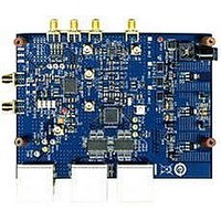
AD9262-EBZ
Description
BOARD EVALUATION FOR AD9262
Manufacturer
Analog Devices Inc
Specifications of AD9262-EBZ
Design Resources
Interfacing ADL5382 to AD9262 as an RF-to-Bits Solution (CN0062)
Number Of Adc's
2
Number Of Bits
16
Sampling Rate (per Second)
160M
Data Interface
Serial, SPI™
Inputs Per Adc
1 Differential
Input Range
2 Vpp
Power (typ) @ Conditions
487mW @ 40MSPS
Voltage Supply Source
Analog and Digital
Operating Temperature
-40°C ~ 85°C
Utilized Ic / Part
AD9262
Silicon Manufacturer
Analog Devices
Application Sub Type
ADC
Kit Application Type
Data Converter
Silicon Core Number
AD9262
Kit Contents
Software, Evaluation Board
Lead Free Status / RoHS Status
Lead free / RoHS Compliant


Table 20 shows the corresponding threshold level in dBFS vs.
register setting. If the input signal crosses this level, the ORx pin
is set. In the case where 0x111[5:0] is set to all 0s, the threshold
level is set to the maximum code of 32,767
vides a means of reporting the instantaneous amplitude as it
crosses a user-provided threshold. This gives the user a sense
of the signal level without needing to perform a full power
measurement.
The user has the ability to select how the overrange conditions
are reported, and this is controlled through Register 0x111 via
AUTORST, OR_IND, and ORTHRESH (see Table 21). By
enabling the AUTORST bit, Register 0x111[7], if an overrange
occurs, the ADC automatically resets itself. The ORx pins remain
high until the automatic reset has completed. If an analog trip
Table 20. OR Threshold Levels
0x111[5:0]
1
2
3
4
5
6
7
8
9
A
B
C
D
E
F
10
11
12
13
14
15
Table 21. ORx Conditions
ORx Conditions
Normal, Reset Off
Digital Threshold,
Full Overrange,
Data Valid, No Reset
Normal, Reset On
Digital Threshold,
Full Overrange,
Data Valid,
Reset Off
Reset Off
Reset On
Reset On
Reset On
Threshold (dBFS)
−36.12
−30.10
−26.58
−24.08
−22.14
−20.56
−19.22
−18.06
−17.04
−16.12
−15.29
−14.54
−13.84
−13.20
−12.60
−12.04
−11.51
−11.02
−10.56
−10.10
−9.68
AUTORST
0
0
0
0
1
1
1
1
OR_IND
0
0
1
1
0
0
1
1
10
. This feature pro-
0x111[5:0]
16
17
18
19
1A
1B
1C
1D
1E
1F
20
21
22
23
24
25
26
27
28
29
2A
ORTHRESH[5:0]
0
0
1
0
0
1
Rev. A | Page 25 of 32
>0
>0
ORTHRESH[4:0]
00000
X
X
00000
X
X
Threshold (dBFS)
−9.28
−8.89
−8.52
−8.16
−7.82
−7.50
−7.18
−6.88
−6.58
−6.30
−6.02
−5.75
−5.49
−5.24
−5.00
−4.76
−4.53
−4.30
−4.08
−3.87
−3.66
occurs, the modulator resets itself after 16 consecutive clock
cycles of overrange.
If the AD9262 is used in a system that incorporates automatic
gain control (AGC), the ORx signal can be used to indicate that
the signal amplitude should be reduced. This may be particularly
effective for use in maximizing the signal dynamic range if the
signal includes high occurrence components that occasionally
exceed full scale by a small amount.
TIMING
The AD9262 provides a data clock out (DCO) pin to assist in
capturing the data in an external register. The data outputs are
valid on the rising edge of DCO, unless changed by setting
Serial Register 0x16[7] (see the Serial Port Interface (SPI)
section). See Figure 2 for a graphical timing description.
Digital trip: if 16-bit output > 32,767, ORx = 1, else ORx = 0
Digital threshold: if 16-bit output > ORTHRESH, ORx = 1,
else ORx = 0
If analog trip or digital trip, ORx = 1, else ORx = 0
Digital trip: if 16-bit output > 32,767, ORx = 1, else ORx = 0
Digital threshold: if 16-bit output > ORTHRESH, ORx = 1,
else ORx = 0
If analog trip or digital trip ORx = 1 else ORx = 0
If analog trip or digital trip or calibration, ORx = 0 else ORx = 1
Description
If analog trip or digital trip or calibration, ORx = 0, else ORx = 1
0x111[5:0]
2B
2C
2D
2E
2F
30
31
32
33
34
35
36
37
38
39
3A
3B
3C
3D
3E
3F
Threshold (dBFS)
−3.45
−3.25
−3.06
−2.87
−2.68
−2.50
−2.32
−2.14
−1.97
−1.80
−1.64
−1.48
−1.32
−1.16
−1.00
−0.86
−0.71
−0.56
−0.42
−0.28
−0.14
AD9262
Related parts for AD9262-EBZ
Image
Part Number
Description
Manufacturer
Datasheet
Request
R

Part Number:
Description:
BOARD EVALUATION 10MHZ AD9262
Manufacturer:
Analog Devices Inc
Datasheet:
Part Number:
Description:
BOARD EVALUATION 5MHZ AD9262
Manufacturer:
Analog Devices Inc
Datasheet:

Part Number:
Description:
±1.7g Dual-Axis IMEMS Accelerometer Evaluation Board
Manufacturer:
Analog Devices Inc
Datasheet:

Part Number:
Description:
Inertial Sensor Evaluation System
Manufacturer:
Analog Devices Inc
Datasheet:
Part Number:
Description:
Manufacturer:
Analog Devices Inc
Datasheet:
Part Number:
Description:
Manufacturer:
Analog Devices Inc
Datasheet:
Part Number:
Description:
Manufacturer:
Analog Devices Inc
Datasheet:
Part Number:
Description:
Manufacturer:
Analog Devices Inc
Datasheet:
Part Number:
Description:
Manufacturer:
Analog Devices Inc
Datasheet:
Part Number:
Description:
Manufacturer:
Analog Devices Inc
Datasheet:
Part Number:
Description:
Manufacturer:
Analog Devices Inc
Datasheet:
Part Number:
Description:
Manufacturer:
Analog Devices Inc
Datasheet:
Part Number:
Description:
Manufacturer:
Analog Devices Inc
Datasheet: