AD9262-5EBZ Analog Devices Inc, AD9262-5EBZ Datasheet - Page 16
AD9262-5EBZ
Manufacturer Part Number
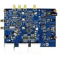
AD9262-5EBZ
Description
BOARD EVALUATION 5MHZ AD9262
Manufacturer
Analog Devices Inc
Specifications of AD9262-5EBZ
Design Resources
Interfacing ADL5382 to AD9262 as an RF-to-Bits Solution (CN0062)
Number Of Adc's
2
Number Of Bits
16
Sampling Rate (per Second)
160M
Data Interface
Serial, SPI™
Inputs Per Adc
1 Differential
Input Range
1 Vpp
Power (typ) @ Conditions
547mW @ 40MSPS
Voltage Supply Source
Analog and Digital
Operating Temperature
-40°C ~ 85°C
Utilized Ic / Part
AD9262
Silicon Manufacturer
Analog Devices
Application Sub Type
ADC
Kit Application Type
Data Converter
Silicon Core Number
AD9262
Kit Contents
Software, Evaluation Board
Lead Free Status / RoHS Status
Lead free / RoHS Compliant


AD9262
THEORY OF OPERATION
The AD9262 uses a continuous time Σ-Δ modulator to convert
the analog input to a digital word. The digital word is processed
by the decimation filter and rate-adjusted by the sample rate
converter (see Figure 37). The modulator consists of a continuous
time loop filter preceding a quantizer that samples at f
640 MSPS. This produces an oversampling ratio (OSR) of 32 for
a 10 MHz input bandwidth. The output of the quantizer is fed
back to a DAC that ideally cancels the input signal. The incom-
plete input cancellation residue is filtered by the loop filter and
is used to form the next quantizer sample.
The quantizer produces a nine-level digital word. The quantization
noise is spread uniformly over the Nyquist band (see Figure 38),
but the feedback loop causes the quantization noise present in
the nine-level output to have a nonuniform spectral shape. This
noise-shaping technique (see Figure 39) pushes the in-band
noise out of band; therefore, the amount of quantization noise
in the frequency band of interest is minimal.
The digital decimation filter that follows the modulator removes
the large out-of-band quantization noise (see Figure 40), while
also reducing the data rate from f
PLL is enabled, the sample rate converter generates samples at
the same frequency as the input clock frequency. If the internal
PLL is disabled, the sample rate converter can be programmed
to give an output frequency that is a divide ratio of the modulator
clock. The sample rate converter is designed to attenuate images
outside the band of interest (see Figure 41).
+
BAND OF INTEREST
BAND OF INTEREST
–
LOOP FILTER
MODULATOR
H(f)
Figure 37. Σ-Δ Modulator Overview
Figure 38. Quantization Noise
Figure 39. Noise Shaping
QUANTIZATION NOISE
QUANTIZER
ADC
NOISE SHAPING
MOD
DECIMATION
to f
FILTER
MOD
/16. If the internal
SAMPLE RATE
CONVERTER
f
SRC
f
MOD
MOD
/2
MOD
/2
=
Rev. A | Page 16 of 32
ANALOG INPUT CONSIDERATIONS
The continuous time modulator removes the need for an anti-
alias filter at the input to the AD9262. A discrete time converter
aliases signals around the sample clock frequency and its multiples
to the band of interest (see Figure 42). Therefore, an external
antialias filter is needed to reject these signals.
In contrast, the continuous time Σ-Δ modulator used within the
AD9262 has inherent antialiasing. The antialiasing property
results from sampling occurring at the output of the loop filter
(see Figure 43), and thus aliasing occurs at the same point in the
loop as quantization noise is injected; aliases are shaped by the
same mechanism as quantization noise. The quantization noise
transfer function, NTF(f), has zeros in the band of interest and in
all alias bands because NTF(f) is a discrete time transfer function,
whereas the loop filter transfer function, LF(f), is a continuous
time transfer function, which introduces poles only in the band
of interest. The signal transfer function, being the product of
NTF(f) and LF(f), only has zeros in alias bands and therefore
suppresses all aliases.
INP UT
LOOP FILTER
BAND OF INTEREST
BAND OF INTEREST
LF(f)
H(z)
DESIRED
INPUT
Figure 40. Digital Filter Cutoff Frequency
Figure 43. Continuous Time Converter
Figure 42. Discrete Time Converter
f
Figure 41. Sample Rate Converter
MOD
DIGITAL FILTER CUTOFF FREQUENCY
f
UNDESIRED
OUT
QUANTIZATION
SIGNAL
/2
f
NOISE
f
MOD
S
/32
ADC
OUTPUT
NTF(f)
L F (f)
f
OUT
f
S
/2
f
f
MOD
MOD
f
MOD
f
MOD
/16
/16
f
Related parts for AD9262-5EBZ
Image
Part Number
Description
Manufacturer
Datasheet
Request
R

Part Number:
Description:
BOARD EVALUATION 10MHZ AD9262
Manufacturer:
Analog Devices Inc
Datasheet:
Part Number:
Description:
BOARD EVALUATION FOR AD9262
Manufacturer:
Analog Devices Inc
Datasheet:

Part Number:
Description:
±1.7g Dual-Axis IMEMS Accelerometer Evaluation Board
Manufacturer:
Analog Devices Inc
Datasheet:

Part Number:
Description:
Inertial Sensor Evaluation System
Manufacturer:
Analog Devices Inc
Datasheet:
Part Number:
Description:
Manufacturer:
Analog Devices Inc
Datasheet:
Part Number:
Description:
Manufacturer:
Analog Devices Inc
Datasheet:
Part Number:
Description:
Manufacturer:
Analog Devices Inc
Datasheet:
Part Number:
Description:
Manufacturer:
Analog Devices Inc
Datasheet:
Part Number:
Description:
Manufacturer:
Analog Devices Inc
Datasheet:
Part Number:
Description:
Manufacturer:
Analog Devices Inc
Datasheet:
Part Number:
Description:
Manufacturer:
Analog Devices Inc
Datasheet:
Part Number:
Description:
Manufacturer:
Analog Devices Inc
Datasheet:
Part Number:
Description:
Manufacturer:
Analog Devices Inc
Datasheet: