AD9262-5EBZ Analog Devices Inc, AD9262-5EBZ Datasheet - Page 7
AD9262-5EBZ
Manufacturer Part Number
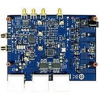
AD9262-5EBZ
Description
BOARD EVALUATION 5MHZ AD9262
Manufacturer
Analog Devices Inc
Specifications of AD9262-5EBZ
Design Resources
Interfacing ADL5382 to AD9262 as an RF-to-Bits Solution (CN0062)
Number Of Adc's
2
Number Of Bits
16
Sampling Rate (per Second)
160M
Data Interface
Serial, SPI™
Inputs Per Adc
1 Differential
Input Range
1 Vpp
Power (typ) @ Conditions
547mW @ 40MSPS
Voltage Supply Source
Analog and Digital
Operating Temperature
-40°C ~ 85°C
Utilized Ic / Part
AD9262
Silicon Manufacturer
Analog Devices
Application Sub Type
ADC
Kit Application Type
Data Converter
Silicon Core Number
AD9262
Kit Contents
Software, Evaluation Board
Lead Free Status / RoHS Status
Lead free / RoHS Compliant


Evaluation Board User Guide
SUPPORTING HARDWARE AND SOFTWARE
The AD9262 can only be evaluated using the HSC-ADC-
EVALCZ high speed ADC data capture card in conjunction
with the VisualAnalog data capture and analysis software.
The SPIController software is used to configure the AD9262
and the AD9516 to the appropriate register settings.
SOFTWARE
Manuals for VisualAnalog, the SPIController software, and
the HSC-ADC-EVALCZ data capture hardware are included
on the CD in the evaluation board package. It is recommended
that the software be installed before connecting the hardware.
VisualAnalog relies on the Microsoft .NET framework version 2,
which is also included on the package CD. The .NET frame-
work should be installed before installing VisualAnalog. The
SPIController software should also be installed.
HARDWARE
The AD9262 evaluation board and the HSC-ADC-EVALCZ
data capture card are powered from a wall-connected switching
power supply. The switching power supplies have different
output voltages. Connect the 6 V power supply to the AD9262
evaluation board and the 5 V power supply to the HSC-ADC-
EVALCZ data capture board. With the HSC-ADC-EVALCZ
data capture board powered on and the VisualAnalog software
installed, connect the USB cable to the PC and follow all the
Found new hardware prompts, using the default driver each time.
AD9262 SPI CONTROLLER
Upon successful software installation and hardware setup, start
the AD9262 SPIController software. By default, the software
recognizes the AD9262 evaluation board and loads the correct
SPIController profile. If it does not, point the software to the
following file: AD9262_16Bit_10MSspiR03.cfg.
The AD9262 SPIController has four tabs. When correctly
configured, a message appears on the CHIP ID subpane
reporting that the AD9262 is interfaced (see Figure 8).
Rev. 0 | Page 7 of 24
AD9516 SPI CONTROLLER
Open another instance of the SPIController for control of the
AD9516. If a box titled Read Test Failure appears, click Ignore
to open the SPIController. This error occurs because the
software has not been configured correctly to read from the
chip. Use the following procedure to appropriately configure the
SPIController to read and write to the AD9516:
1.
2.
3.
From the File menu, select CfgOpen; then select
AD9516spiengR03.cfg.
When a Calibration File Error! message appears as shown
in Figure 9, click OK.
Select Config and then Controller Dialog and make sure
that FIFO Chip Sel is set to 2 and that USB Chan # is set
to the same value as the AD9262 SPIController Cfg dialog
(see Figure 10).
Figure 8. AD9262 SPIController
Figure 9.
UG-051
Related parts for AD9262-5EBZ
Image
Part Number
Description
Manufacturer
Datasheet
Request
R

Part Number:
Description:
BOARD EVALUATION 10MHZ AD9262
Manufacturer:
Analog Devices Inc
Datasheet:
Part Number:
Description:
BOARD EVALUATION FOR AD9262
Manufacturer:
Analog Devices Inc
Datasheet:

Part Number:
Description:
±1.7g Dual-Axis IMEMS Accelerometer Evaluation Board
Manufacturer:
Analog Devices Inc
Datasheet:

Part Number:
Description:
Inertial Sensor Evaluation System
Manufacturer:
Analog Devices Inc
Datasheet:
Part Number:
Description:
Manufacturer:
Analog Devices Inc
Datasheet:
Part Number:
Description:
Manufacturer:
Analog Devices Inc
Datasheet:
Part Number:
Description:
Manufacturer:
Analog Devices Inc
Datasheet:
Part Number:
Description:
Manufacturer:
Analog Devices Inc
Datasheet:
Part Number:
Description:
Manufacturer:
Analog Devices Inc
Datasheet:
Part Number:
Description:
Manufacturer:
Analog Devices Inc
Datasheet:
Part Number:
Description:
Manufacturer:
Analog Devices Inc
Datasheet:
Part Number:
Description:
Manufacturer:
Analog Devices Inc
Datasheet:
Part Number:
Description:
Manufacturer:
Analog Devices Inc
Datasheet: