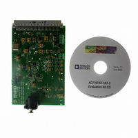
EVAL-AD7767-1EDZ Analog Devices Inc, EVAL-AD7767-1EDZ Datasheet - Page 12

EVAL-AD7767-1EDZ
Manufacturer Part Number
EVAL-AD7767-1EDZ
Description
BOARD EVAL AD7767-1 64KSPS 111DB
Manufacturer
Analog Devices Inc
Specifications of EVAL-AD7767-1EDZ
Number Of Adc's
1
Number Of Bits
24
Sampling Rate (per Second)
64k
Data Interface
Serial
Inputs Per Adc
1 Differential
Input Range
±VREF
Power (typ) @ Conditions
10.5mW @ 64kSPS
Voltage Supply Source
Analog and Digital
Operating Temperature
-40°C ~ 105°C
Utilized Ic / Part
AD7767-1
Lead Free Status / RoHS Status
Lead free / RoHS Compliant
EVAL-AD7767/67-1/67-2
LINEARITY
The Linearity tab allows the user to evaluate the linearity of the
device, creating an accumulating histogram for a non-coherent
sampling system. Figure 9 shows an example of a linearity test
conducted using the clipped sine-wave method. When
evaluating linearity it is Max Hits Per Code that determines the
duration it takes to complete the data capture. In this case, Max
Hits Per Code was set to 400. This is the recommended
number of hits per code for evaluation of the AD7767/AD7767-
1/AD7767-2 devices.
For the results shown in Figure 9 an Audio Precision 2700 series
sine source was used to apply a 10.5Vpp (as per Ap front panel)
to the AD7767. This input amplitude provides a clipped output
from the ADC. The frequency of the sine wave used was
324.25Hz. It is important that the frequency of the input is not
an integer division of the ADC sampling rate, which was set to
1.024MHz in this case. Using a setting of 400 hits per code the
test took approximately 25 to 30 minutes.
The AD7767/AD7767-1/AD7767-2 software is configured to
generate 21-bit linearity plots. Running the AD7767 linearity
with greater than 400 hits per code will show improved INL
performance. The INL results are graphed with ppm on the y-
axis and bins on the x-axis. Each bin represents eight 24-Bit
codes.
The DNL plots prove only that there are no missing codes to
21-bits. This is set to 21 bits due to a hardware limitation on the
CED board. The SRAM address is limited to 21-bits. Plots to
show 24-bit no-missing codes are on the AD7767 datasheet.
To initiate conversions and perform the linearity routine the
Rev. PrB | Page 12 of 26
user must click on the Get Linearity Data button. This
instructs the EVAL-CED1Z board to take the required number
of samples at the required frequency from the evaluation board.
Both the Max Hits Per Code control and the Get Linearity
Data button are located on the top right hand side of the
Linearity tab.
The samples are then uploaded and processed. The INL and
DNL are calculated during the processing. The results are
displayed in the Histogram, DNL, INL and Summary tab
buttons.
The linearity analysis is displayed at the bottom of the Linearity
tab. This section contains information about the samples taken
as well as the worst-case positive (WCP) and worst-case
negative (WCN) INL and DNL data.
Sub tabs on the Linearity Tabs are:
Histogram Tab
This tab displays a Histogram of the captured ADC codes.
DNL Tab
This tab displays a plot of the DNL results.
INL Tab
This tab displays a plot of the INL results.
Summary Tab
This tab displays the histogram, INL and DNL plots together on
one screen.
Preliminary Technical Data


