MCP3901EV-MCU16 Microchip Technology, MCP3901EV-MCU16 Datasheet - Page 11
MCP3901EV-MCU16
Manufacturer Part Number
MCP3901EV-MCU16
Description
BOARD EVAL FOR 2CH ADC MCP3901
Manufacturer
Microchip Technology
Datasheets
1.MCP3901A0-ISS.pdf
(60 pages)
2.MCP3901A0-ISS.pdf
(30 pages)
3.MCP3901EV-MCU16.pdf
(38 pages)
4.MCP3901EV-MCU16.pdf
(38 pages)
Specifications of MCP3901EV-MCU16
Number Of Adc's
2
Number Of Bits
24
Data Interface
SPI™
Inputs Per Adc
1 Differential
Input Range
±1 V
Voltage Supply Source
Analog and Digital
Operating Temperature
-40°C ~ 85°C
Utilized Ic / Part
MCP3901
Silicon Manufacturer
Microchip
Application Sub Type
ADC
Kit Application Type
Data Converter
Silicon Core Number
MCP3901, PIC24F, PIC24H, DsPIC33, PIC18F86J55
Kit Contents
Board
Lead Free Status / RoHS Status
Lead free / RoHS Compliant


1.2
FIGURE 1-2:
© 2009 Microchip Technology Inc.
PIM Module
PIM MODULE / MCP3901 CONNECTION AND PERIPHERAL USAGE
OVERVIEW
RF2/U1RX
RF3/U1TX
IC4/RD11
IC3/RD10
INT3/RA4
SDO1/RF8
SCK1/RF6
SDI1/RF7
OC1/RD0
RB8/9/10
RA9/10
RA5
RA4
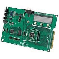
The MCP3901 ADC Evaluation Board for 16-Bit MCUs contains a 100-pin PIM socket
compatible with Microchip’s PIM modules. The system comes with 2 PIM modules: the
PIC24FJ128GA010 and dsPIC33FJ256GA710.
A complete description of the firmware programmed with these two modules is
available in Chapter 1. “Hardware Description”.
Digital Connection Overview PIM/MCP3901 Connections.
Ports A, B, and D are used for signals such as push buttons, output LEDs, CS and
MCLR (for MCP3901 data mode setting). Output Capture 1 is used for MCP3901’s
clock generation. Serial communication is achieved through the MSSP module 1.
RESET
MDAT0
MDAT1
SCK
SDO
DR
CS
SDI
D6 D7
CONTROL SWITCHES (X3)
UART SERIAL TO PC COMMUNICATION
SPI Serial
Interface
DGND
(Green)
DVDD
Translation
Modulator
Block
Output
Hardware Description
Clock Generation/
Phase Correction
MCP3901
Current Boost
Delta Sigma
Multi-Level
Modulator
Delta Sigma
Multi-Level
Modulator
OSC2
Circuit
OSC1
PGA
PGA
AGND
INT
V
REF
+
+
-
-
AVDD
DS51845A-page 7
CH1+
CH1-
CH0-
CH0+
Related parts for MCP3901EV-MCU16
Image
Part Number
Description
Manufacturer
Datasheet
Request
R

Part Number:
Description:
Manufacturer:
Microchip Technology Inc.
Datasheet:
Part Number:
Description:
Manufacturer:
Microchip Technology Inc.
Datasheet:
Part Number:
Description:
Manufacturer:
Microchip Technology Inc.
Datasheet:
Part Number:
Description:
Manufacturer:
Microchip Technology Inc.
Datasheet:
Part Number:
Description:
Manufacturer:
Microchip Technology Inc.
Datasheet:
Part Number:
Description:
Manufacturer:
Microchip Technology Inc.
Datasheet:
Part Number:
Description:
Manufacturer:
Microchip Technology Inc.
Datasheet:
Part Number:
Description:
Manufacturer:
Microchip Technology Inc.
Datasheet: