MCP3221DM-PCTL Microchip Technology, MCP3221DM-PCTL Datasheet - Page 12
MCP3221DM-PCTL
Manufacturer Part Number
MCP3221DM-PCTL
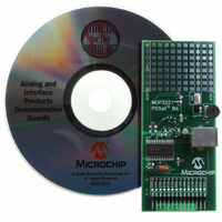
Description
BOARD DEMO FOR PICTAIL MCP3221
Manufacturer
Microchip Technology
Series
PICtail™r
Type
A/Dr
Datasheets
1.MCP3221A5T-IOT.pdf
(28 pages)
2.MCP3221DM-PCTL.pdf
(20 pages)
3.MCP3221DM-PCTL.pdf
(20 pages)
Specifications of MCP3221DM-PCTL
Number Of Adc's
1
Number Of Bits
12
Sampling Rate (per Second)
22.3k
Data Interface
Serial
Inputs Per Adc
1 Single Ended
Voltage Supply Source
Single Supply
Operating Temperature
-40°C ~ 85°C
Utilized Ic / Part
MCP3221
Product
Data Conversion Development Tools
Resolution
12 bit
Interface Type
USB
Silicon Manufacturer
Microchip
Silicon Core Number
MCP3221
Kit Application Type
Data Converter
Application Sub Type
ADC
Silicon Family Name
PICtail
Kit Contents
Board Cables CD Docs
Rohs Compliant
Yes
For Use With/related Products
MCP3221
Lead Free Status / RoHS Status
Contains lead / RoHS non-compliant
Lead Free Status / RoHS Status
Lead free / RoHS Compliant, Contains lead / RoHS non-compliant
Available stocks
Company
Part Number
Manufacturer
Quantity
Price
Company:

Part Number:
MCP3221DM-PCTL
Manufacturer:
MICROCHIP
Quantity:
12 000


2.4
DS51545B-page 8
MCP3221 PICTAIL™ DEMO BOARD DESCRIPTION
The major components of the MCP3221 PICtail™ Demo Board are listed.
1. MCP3221 device (U1)
2. PICmicro
3. PICkit™ Starter Kit Header (J1)
4. USB Connector (J2)
5. Analog Input and Prototype Area (TP)
6. Input Selection Jumper (JP1)
7. Potentiometer Input (VR1)
For more detailed circuit information, refer to Appendix A. “Schematic and Layouts”
and Appendix B. “Bill Of Materials (BOM)”.
FIGURE 2-1:
2.4.1
The USB power is regulated and filtered before supplying power to the MCP3221
device. The raw USB power supplies the digital voltage to the PICmicro MCU only. This
digital power supply is filtered through the LRC circuit and the 4.1V regulator as it
becomes the analog voltage (A
used as the reference for the mechanical potentiometer. This regulated ratiometric
connection achieves superior performance from the typically noisy PC USB power
supply.
2.4.2
The MCP3221 is an infrared device. The two data lines, SCL and SDA, are connected
from the PICkit Starter Kit header J1 to the appropriate port pins, RC0 and RC1. +5V
and V
header.
2.4.3
The MCP3221 analog input is tied directly to TP1, next to a small area for prototyping.
A mechanical potentiometer is also connected to this node, allowing for a quick DC
evaluation of the device’s function. When the jumper is selected, the wiper of the
mechanical potentiometer is connected to the analog input of the device. When the
jumper is de-selected, the analog input is connected only to TP1 and the prototype
area.
SS
are the other two PICkit Starter Kit connections made on the MCP3221 PICkit
Hardware Power
MCP3221 Interface to PICkit™ 1 Flash Starter Kit
Selecting The Analog Input
®
MCU – PIC16C745 (U2)
MCP3221 PICtail™ Demo Board Block Diagram.
VDD
) for the MCP3221. This analog power supply is also
© 2006 Microchip Technology Inc.
Related parts for MCP3221DM-PCTL
Image
Part Number
Description
Manufacturer
Datasheet
Request
R

Part Number:
Description:
Manufacturer:
Microchip Technology Inc.
Datasheet:
Part Number:
Description:
Manufacturer:
Microchip Technology Inc.
Datasheet:
Part Number:
Description:
Manufacturer:
Microchip Technology Inc.
Datasheet:
Part Number:
Description:
Manufacturer:
Microchip Technology Inc.
Datasheet:
Part Number:
Description:
Manufacturer:
Microchip Technology Inc.
Datasheet:
Part Number:
Description:
Manufacturer:
Microchip Technology Inc.
Datasheet:
Part Number:
Description:
Manufacturer:
Microchip Technology Inc.
Datasheet:
Part Number:
Description:
Manufacturer:
Microchip Technology Inc.
Datasheet: