MCP3421EV Microchip Technology, MCP3421EV Datasheet - Page 15
MCP3421EV
Manufacturer Part Number
MCP3421EV
Description
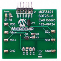
BOARD EVAL FOR MCP3421 SOT23-6
Manufacturer
Microchip Technology
Specifications of MCP3421EV
Design Resources
MCP3421EV Gerber Files
Number Of Adc's
1
Number Of Bits
18
Sampling Rate (per Second)
4
Data Interface
Serial
Inputs Per Adc
1 Single Ended
Input Range
±2.5 V
Voltage Supply Source
Single Supply
Operating Temperature
-40°C ~ 125°C
Utilized Ic / Part
MCP3421
Silicon Manufacturer
Microchip
Application Sub Type
ADC
Kit Application Type
Data Converter
Silicon Core Number
MCP3421
Kit Contents
Board
Rohs Compliant
Yes
Lead Free Status / RoHS Status
Not applicable / Not applicable
Available stocks
Company
Part Number
Manufacturer
Quantity
Price
Company:

Part Number:
MCP3421EV
Manufacturer:
Microchip Technology
Quantity:
135


5.0
5.1
The user operates the device by setting up the device
configuration register using a write command (see
Figure
command (see
operates in two modes: (a) Continuous Conversion
Mode or (b) One-Shot Conversion Mode (single
conversion). This mode selection is made by setting
the O/C bit in the Configuration Register. Refer to
Section 5.2 “Configuration Register” for more
information.
5.1.1
The device performs a Continuous Conversion if the
O/C bit is set to logic “high”. Once the conversion is
completed, RDY bit is toggled to ‘0’ and the result is
placed at the output data register. The device
immediately begins another conversion and overwrites
the output data register with the most recent result. The
device clears the data ready flag (RDY bit = 0) when
the conversion is completed. The device sets the ready
flag bit (RDY bit = 1), if the latest conversion result has
been read by the Master.
• When writing configuration register:
• When reading conversion data:
© 2009 Microchip Technology Inc.
- Setting RDY bit in continuous mode does not
- RDY bit = 0 means the latest conversion
- RDY bit = 1 means the conversion result is
affect anything
result is ready
not updated since the last reading. A new
conversion is under processing and the RDY
bit will be cleared when the new conversion
result is ready
5-2) and reads the conversion data using a read
USING THE MCP3421 DEVICE
Operating Modes
CONTINUOUS CONVERSION
MODE (O/C BIT =
Figure 5-3
and
Figure
1
)
5-4). The device
5.1.2
Once the One-Shot Conversion (single conversion)
Mode is selected, the device performs only one
conversion, updates the output data register, clears the
data ready flag (RDY = 0), and then enters a low power
standby mode. A new One-Shot Conversion is started
again when the device receives a new write command
with RDY = 1.
• When writing configuration register:
• When reading conversion data:
This
recommended for low power operating applications
where the conversion result is needed by request on
demand. During the low current standby mode, the
device consumes less than 1 µA maximum (or 300 nA
typical). For example, if the user collects 18 bit
conversion data once a second in One-Shot
Conversion mode, the device draws only about one
fourth of its total operating current. In this example, the
device consumes approximately 39 µA (145 µA / 3.75
SPS = 39 µA), if the device performs only one
conversion per second (1 SPS) in 18-bit conversion
mode with 3V power supply.
- The RDY bit needs to be set to begin a new
- RDY bit = 0 means the latest conversion
- RDY bit = 1 means the conversion result is
conversion in one-shot mode
result is ready
not updated since the last reading. A new
conversion is under processing and the RDY
bit will be cleared when the new conversion is
done
One-Shot
ONE-SHOT CONVERSION MODE
(O/C BIT =
Conversion
0
)
MCP3421
Mode
DS22003E-page 15
is
highly
Related parts for MCP3421EV
Image
Part Number
Description
Manufacturer
Datasheet
Request
R

Part Number:
Description:
Manufacturer:
Microchip Technology Inc.
Datasheet:
Part Number:
Description:
Manufacturer:
Microchip Technology Inc.
Datasheet:
Part Number:
Description:
Manufacturer:
Microchip Technology Inc.
Datasheet:
Part Number:
Description:
Manufacturer:
Microchip Technology Inc.
Datasheet:
Part Number:
Description:
Manufacturer:
Microchip Technology Inc.
Datasheet:
Part Number:
Description:
Manufacturer:
Microchip Technology Inc.
Datasheet:
Part Number:
Description:
Manufacturer:
Microchip Technology Inc.
Datasheet:
Part Number:
Description:
Manufacturer:
Microchip Technology Inc.
Datasheet: