EVB-USB2512Q36-BAS SMSC, EVB-USB2512Q36-BAS Datasheet - Page 29
EVB-USB2512Q36-BAS
Manufacturer Part Number
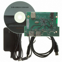
EVB-USB2512Q36-BAS
Description
BOARD EVAL FOR USB2512/USB2512I
Manufacturer
SMSC
Specifications of EVB-USB2512Q36-BAS
Main Purpose
Interface, USB 2.0 Hub
Embedded
No
Utilized Ic / Part
USB2512, USB2512I
Primary Attributes
Dual Port Hub, High Speed (480Mbps), I2C/SMBus
Secondary Attributes
Overcurrent Protection, Port Power Switching, ESD Protection
Interface Type
USB
Operating Supply Voltage
5 V
Product
Interface Modules
Lead Free Status / RoHS Status
Lead free / RoHS Compliant
For Use With/related Products
USB2512
Other names
638-1041
EVB-USB2512Q36-BAS (USB2512/USB2512I)
EVB-USB2512Q36-BAS (USB2512/USB2512I)


USB 2.0 Hi-Speed Hub Controller
Datasheet
Chapter 6 LED Usage Description
SMSC USB251x
6.1
6.1.1
6.1.2
USB2513 and USB2514 (48-pin QFN only) and USB2517/17i SMSC hubs support two different
(mutually exclusive) LED modes. The ‘x’ represents the number of downstream ports. The USB mode
provides up to 14 LED’s that conform to the USB 2.0 specification functional requirements for Green
and Amber LED’s. The LED mode “speed indicator” provides the downstream device connection
speed.
USB Mode 14-Wire
The LED_A_N[x:1] pins are used to provide Green LED support as defined in the USB 2.0
specification. The LED_B_N[x:1] pins are used to provide Amber LED support as defined in the USB
2.0 specification. The USB specification defines the LED’s as port status indicators for the downstream
ports. Please note that no indication of port speed is possible in this mode. The pins are utilized as
follows:
LED_A_N[x:1] = Port [x:1] green LED
LED_B_N[x:1] = Port [x:1] amber LED
LED Mode Speed Indication
The LED_A[x:1]_N pins are used to provide connection status as well as port speed by using dual
color LED's. This scheme requires that the LED's be in the same package, and that a third color is
produced so that the user perceives both LED's as being driven "simultaneously".
The LED_A[x:1] pins used in this mode are connected to x number of dual color LED’s (each LED pair
in a single package). These pins indicate the USB speed of each attached downstream device.
Each dual color LED provides two separate colors (commonly Green and Red). If each of these
separate colors are pulsed on and off at a rapid rate, a user will see a third color (in this example,
Orange). Using this method, 4 different "color" states are possible (Green, Red, Orange, and Off).
LED Functionality
Hub LED pin
3.3 V
Figure 6.1 Dual Color LED Implementation Example
Current Limiting
Purpose
General
Diode
Resistor
DATASHEET
29
D1A (Green LED)
D1B (Red LED)
other Dual Color
Connection to
Diodes
Revision 1.1 (04-26-10)
Related parts for EVB-USB2512Q36-BAS
Image
Part Number
Description
Manufacturer
Datasheet
Request
R

Part Number:
Description:
MCU, MPU & DSP Development Tools USB2512 (STT) 2-Port Eval Board
Manufacturer:
SMSC
Datasheet:

Part Number:
Description:
FAST ETHERNET PHYSICAL LAYER DEVICE
Manufacturer:
SMSC Corporation
Datasheet:
Part Number:
Description:
357-036-542-201 CARDEDGE 36POS DL .156 BLK LOPRO
Manufacturer:
SMSC Corporation
Datasheet:
Part Number:
Description:
357-036-542-201 CARDEDGE 36POS DL .156 BLK LOPRO
Manufacturer:
SMSC Corporation
Datasheet:
Part Number:
Description:
357-036-542-201 CARDEDGE 36POS DL .156 BLK LOPRO
Manufacturer:
SMSC Corporation
Datasheet:
Part Number:
Description:
4-PORT USB2.0 HUB CONTROLLER
Manufacturer:
SMSC Corporation
Datasheet:
Part Number:
Description:
Manufacturer:
SMSC Corporation
Datasheet:
Part Number:
Description:
Manufacturer:
SMSC Corporation
Datasheet:
Part Number:
Description:
FDC37C672ENHANCED SUPER I/O CONTROLLER WITH FAST IR
Manufacturer:
SMSC Corporation
Datasheet:
Part Number:
Description:
COM90C66LJPARCNET Controller/Transceiver with AT Interface and On-Chip RAM
Manufacturer:
SMSC Corporation
Datasheet:
Part Number:
Description:
Manufacturer:
SMSC Corporation
Datasheet:
Part Number:
Description:
Manufacturer:
SMSC Corporation
Datasheet:
Part Number:
Description:
Manufacturer:
SMSC Corporation
Datasheet:
Part Number:
Description:
Manufacturer:
SMSC Corporation
Datasheet: