LMX25121065EVAL/NOPB National Semiconductor, LMX25121065EVAL/NOPB Datasheet - Page 3
LMX25121065EVAL/NOPB
Manufacturer Part Number
LMX25121065EVAL/NOPB
Description
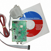
EVALUATION BOARD FOR LMX25121065
Manufacturer
National Semiconductor
Series
PLLatinum™r
Datasheets
1.LMX2512LQ0967NOPB.pdf
(18 pages)
2.LMX2430EVAL.pdf
(8 pages)
3.LMX25121065EVALNOPB.pdf
(24 pages)
Specifications of LMX25121065EVAL/NOPB
Main Purpose
Timing, Frequency Synthesizer
Embedded
No
Utilized Ic / Part
LMX2512
Primary Attributes
Single Fractional-N and Integer-N PLL with VCO
Secondary Attributes
1.065GHz, CodeLoader Graphical User Interface
Lead Free Status / RoHS Status
Lead free / RoHS Compliant
Other names
*LMX25121065EVAL
*LMX25121065EVAL/NOPB
LMX25121065EVAL
*LMX25121065EVAL/NOPB
LMX25121065EVAL


1
The LMX2512 Evaluation Board simplifies evaluation of the LMX2512 Dual PLL with integrated
RF VCO. The board allows for the evaluation of many RF and IF PLL performance parameters
with various control settings including: phase noise, lock time and spurious. The CodeLoader
software gives the user a simple means of programming the IC’s control registers. The board has
sufficient flexibility to allow the user to place an additional on-board supply regulator and TCXO.
The evaluation board circuitry consists of an LMX2512LQ1065 device, an IF VCO and a discrete
IF loop filter.
(IF_OUT) and RF lock detect (LD) outputs, the reference frequency (OSC_IN) input and the
power (VDD_5V) connection. A MICROWIRE
board for connecting to a PC through the parallel printer port. By means of serial port emulation,
the CodeLoader software facilitates the LMX2512LQ1065 internal register programming for
evaluation and measurement.
2
The fully assembled LMX2512 Evaluation Board is factory tested. Follow the instructions below
to set up the hardware platform for the measurement of interest.
2.1.1
2.1.2
LMX2512LQ1065
•
•
•
•
1. Connect the RF_OUT or IF_OUT output port to the input of the spectrum analyzer for
2. Connect an RF signal generator or TCXO to the OSC_IN port of the evaluation board.
3. Plug the DB25 connector end of the cable assembly to the parallel port of the PC.
General Description
Setup
Recommended Test Equipment
Spectrum analyzer with operating frequency range > 2 GHz
Modulation domain analyzer
Low noise signal source adjusted to desired reference frequency
DC power supply with adjustable voltage output
Connection and Setup
phase noise and reference spur measurement or to the input of the modulation domain
analyzer for lock time measurement. Connect the unused port to a suitable 50-ohm
termination.
Set the RF frequency to the desired reference frequency, 19.68 MHz for the default case.
Set the RF level to 1 dBm (~0.7 Vpp).
Connect the other end of the cable to the on-board 10 Pin Header (uWire) with the strip
on the cable at the end opposite the end with the uWire label. Refer to Appendix E for
more details. Alternatively, refer to the
Semiconductor’s Wireless Communications website: wireless.national.com.
SMA flange mount connectors provide for the RF VCO (RF_OUT), IF VCO
LMX2512LQ1065 EVALUATION BOARD OPERATING INSTRUCTIONS
February 19, 2003
CodeLoader Operating Instructions
cable assembly is bundled with the evaluation
from National
1
Related parts for LMX25121065EVAL/NOPB
Image
Part Number
Description
Manufacturer
Datasheet
Request
R

Part Number:
Description:
National Semiconductor [8-Bit D/A Converter]
Manufacturer:
National Semiconductor
Datasheet:
Part Number:
Description:
National Semiconductor [Media Coprocessor]
Manufacturer:
National Semiconductor
Datasheet:
Part Number:
Description:
Digitally Controlled Tone and Volume Circuit with Stereo Audio Power Amplifier, Microphone Preamp Stage and National 3D Sound
Manufacturer:
National Semiconductor
Datasheet:
Part Number:
Description:
Digitally Controlled Tone and Volume Circuit with Stereo Audio Power Amplifier, Microphone Preamp Stage and National 3D Sound
Manufacturer:
National Semiconductor
Datasheet:
Part Number:
Description:
AC97 Rev 2 Codec with Sample Rate Conversion and National 3D Sound
Manufacturer:
National Semiconductor
Part Number:
Description:
Manufacturer:
National Semiconductor
Datasheet:
Part Number:
Description:
Manufacturer:
National Semiconductor
Datasheet:
Part Number:
Description:
General Purpose, Low Voltage, Low Power, Rail-to-Rail Output Operational Amplifiers
Manufacturer:
National Semiconductor
Datasheet:
Part Number:
Description:
8-bit 20 MSPS flash A/D converter.
Manufacturer:
National Semiconductor
Datasheet:
Part Number:
Description:
Low Noise Quad Operational Amplifier
Manufacturer:
National Semiconductor
Datasheet:
Part Number:
Description:
Quad Differential Line Receivers
Manufacturer:
National Semiconductor
Datasheet:
Part Number:
Description:
Quad High Speed Trapezoidal? Bus Transceiver
Manufacturer:
National Semiconductor
Datasheet:
Part Number:
Description:
Dual Line Receiver
Manufacturer:
National Semiconductor
Datasheet:
Part Number:
Description:
TTL to 10k ECL Level Translator with Latch
Manufacturer:
National Semiconductor
Datasheet: