KIT35XS3400EVBE Freescale Semiconductor, KIT35XS3400EVBE Datasheet - Page 9
KIT35XS3400EVBE
Manufacturer Part Number
KIT35XS3400EVBE
Description
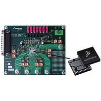
KIT EVALUATION FOR MC35XS3400
Manufacturer
Freescale Semiconductor
Specifications of KIT35XS3400EVBE
Main Purpose
Automotive Lighting
Utilized Ic / Part
*
Primary Attributes
4 protected high-side switches
Secondary Attributes
SPI Interface
Silicon Manufacturer
Freescale
Silicon Core Number
MC35XS3400
Kit Application Type
Power Management
Application Sub Type
EXtreme Switch
Kit Contents
Evaluation Board, CD
Rohs Compliant
Yes
Lead Free Status / RoHS Status
Lead free / RoHS Compliant
Embedded
-
Lead Free Status / Rohs Status
Lead free / RoHS Compliant


8
Freescale Semiconductor
TEST POINTS
Name
JP10
JP11
JP12
JP1
JP2
JP3
JP4
JP5
JP6
JP7
JP9
Jumper Connections
Allows independent control of each high-side switch output
1-2 selection: outputs are controlled via SPIGen or connectors J7 - J10
2-3 selection: direct control of the output, appropriate output is ON
FSI selection
1-2: FSI terminal connected through 6k8 Ohm resistor to ground
2-3: FSI terminal connected to ground
Allows wake up function of IC.
1-2 selection will give external control through connector J12.
2-3 selection is to wake up from battery voltage, i.e. in the case of ignition.
Selection of supplying of FSB LED
1-2: FSB LED D1 connected to VDD (5V)
2-3: FSB LED D1 connected to Vpwr (12V)
Source of VDD (+5V)
1-2: +5V is provided by PC via parallel cable
Floating: +5V must be connected to J11, otherwise the device is in fail-safe mode (the output states depend on R11 value).
Connection of RSTB input
1-2 position: control through SPIGen
Floating: RSTB is ground. This means that the IC is in sleep mode.
Connection of VDD to the device
1-2 position: VDD connected to the device
Floating: Device without VDD
R8 bypassing
1-2 position: R8 is bypassed with 0Ohms. For higher speed of SPI (MCU control of the device only)
Floating: Low speed SPI operation with SPIGen software
Several test points are presented on the evaluation board to check some signals using oscilloscope if necessary.
KIT eXtreme Switch Evaluation
Description
Board, Rev. 1.0
Jumper Connections
9
Related parts for KIT35XS3400EVBE
Image
Part Number
Description
Manufacturer
Datasheet
Request
R

Part Number:
Description:
Manufacturer:
Freescale Semiconductor, Inc
Datasheet:
Part Number:
Description:
Manufacturer:
Freescale Semiconductor, Inc
Datasheet:
Part Number:
Description:
Manufacturer:
Freescale Semiconductor, Inc
Datasheet:
Part Number:
Description:
Manufacturer:
Freescale Semiconductor, Inc
Datasheet:
Part Number:
Description:
Manufacturer:
Freescale Semiconductor, Inc
Datasheet:
Part Number:
Description:
Manufacturer:
Freescale Semiconductor, Inc
Datasheet:
Part Number:
Description:
Manufacturer:
Freescale Semiconductor, Inc
Datasheet:
Part Number:
Description:
Manufacturer:
Freescale Semiconductor, Inc
Datasheet:
Part Number:
Description:
Manufacturer:
Freescale Semiconductor, Inc
Datasheet:
Part Number:
Description:
Manufacturer:
Freescale Semiconductor, Inc
Datasheet:
Part Number:
Description:
Manufacturer:
Freescale Semiconductor, Inc
Datasheet:
Part Number:
Description:
Manufacturer:
Freescale Semiconductor, Inc
Datasheet:
Part Number:
Description:
Manufacturer:
Freescale Semiconductor, Inc
Datasheet:
Part Number:
Description:
Manufacturer:
Freescale Semiconductor, Inc
Datasheet:
Part Number:
Description:
Manufacturer:
Freescale Semiconductor, Inc
Datasheet: