KIT34673EPEVBE Freescale Semiconductor, KIT34673EPEVBE Datasheet - Page 11
KIT34673EPEVBE
Manufacturer Part Number
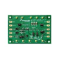
KIT34673EPEVBE
Description
KIT EVALUATION FOR MC34673
Manufacturer
Freescale Semiconductor
Type
Battery Managementr
Specifications of KIT34673EPEVBE
Main Purpose
Power Management, Battery Charger
Embedded
No
Utilized Ic / Part
MC34673
Primary Attributes
1 Cell- Li-Ion
Secondary Attributes
LED Status Indicators
Input Voltage
2.6 V
Maximum Operating Temperature
+ 85 C
Minimum Operating Temperature
- 40 C
Product
Power Management Modules
Supply Current
1.2 A
Silicon Manufacturer
Freescale
Silicon Core Number
MC34673
Kit Application Type
Power Management - Battery
Application Sub Type
Battery Charger
Kit Contents
Evaluation Board, CD
Rohs Compliant
Yes
Lead Free Status / RoHS Status
Lead free / RoHS Compliant
For Use With/related Products
MC34673


battery charger in a tiny package. It uses current, voltage and
temperature control loops to regulate the charge current. It
has up to 28V input voltage rating, which makes the handheld
device safe even when connected to a wrong AC adapter.
one resistor to build a fully functional charger for space-
limited applications such as PDAs, cell phones, portable
video game players and digital still cameras. Its ultra high-
accuracy (±0.7%) output voltage and temperature-limited
charging current offer additional battery safety during
charging.
INPUT SUPPLY (VIN)
with a 1.0µF capacitor.
POWER PRESENT INDICATOR (PPR)
The PPR-pin output is only determined by the input voltage,
not other conditions such as the EN pin input. The output is
low if V
least 12.0mA current to drive a LED indicator.
CHARGE INDICATOR (CHG)
output is low when the MC34673 is charging, until the EOC
conditions are reached. This pin is capable to sink at least
12.0mA current to drive a LED indicator.
ENABLE (EN)
to ground by a weak current source. When left floating, the
charger is enabled. Pulling this pin to high voltage externally
disables the charger.
GROUND (GND)
FAST CHARGE INDICATOR (FAST)
whether or not the battery voltage is higher than the trickle-
Analog Integrated Circuit Device Data
Freescale Semiconductor
The MC34673 is a fully-integrated Li-Ion and Li-Polymer
The MC34673 requires only two external capacitors and
The supply input. This pin should be bypassed to ground
Open-drain logic output to indicate the input power status.
Open-drain logic output to indicate the charge status. The
Active-low enable logic Input. This pin is internally pulled
Ground.
When charging, this open-drain logic output indicates
IN
is higher than V
POR
. This pin is capable to sink at
FUNCTIONAL DESCRIPTION
FUNCTIONAL PIN DESCRIPTION
INTRODUCTION
external resistor (R
proportional to the charge current, so the system can monitor
the charge current during the whole charge cycle. The EOC
current threshold is preset to 10% of the CC-mode current.
For a deeply discharged battery with a voltage lower than
2.7V, the MC34673 charges the battery with a trickle-mode
current, which is 20% of the CC-mode current.
power status and the charge status to MCUs, or users via
LEDs.
mode threshold. This pin is capable to sink more than 0.3mA
current. When the charger is on, this pin outputs a logic low
signal if the battery voltage is higher than the trickle-mode
threshold. When the charger is in the shutdown mode or in
any fault conditions, this pin outputs high-impedance.
CC-MODE CURRENT SETTING AND CHARGE
CURRENT MONITOR (ISET)
a resistor, R
charging in the CC-mode, the voltage at this pin is 1.0V. The
voltage reduces proportionally as the charge current reduces
in the CV-mode. During the whole charge cycle, the voltage
at this pin can be used to monitor the charge current using the
following equation:
where I
programmed CC-mode current, and V
the ISET pin during the whole charge cycle.
CHARGER OUTPUT (BAT)
charged. Bypass to ground with a 2.2µF or higher capacitor.
EXPOSED PAD (EPAD)
on the PCB to enhance the thermal conductivity. The pad
must be connected to GND electrically.
I
The CC-mode current can be programmed with an
Three indication outputs make it easy to report the input
The CC-mode current, I
Charger output pin. Connect this pin to the battery being
Exposed pad. Must be soldered on the large ground plane
BAT
BAT
=
V
-------------- - I
1.0V
is the actual charge current, I
ISET
ISET
, between this pin and the ground. When
⋅
CHG
ISET
). The voltage across this resistor is
CHG
, is programmed by connecting
FUNCTIONAL DESCRIPTION
ISET
CHG
is the voltage of
INTRODUCTION
is the
equ. 1
34673
11
Related parts for KIT34673EPEVBE
Image
Part Number
Description
Manufacturer
Datasheet
Request
R

Part Number:
Description:
Manufacturer:
Freescale Semiconductor, Inc
Datasheet:
Part Number:
Description:
Manufacturer:
Freescale Semiconductor, Inc
Datasheet:
Part Number:
Description:
Manufacturer:
Freescale Semiconductor, Inc
Datasheet:
Part Number:
Description:
Manufacturer:
Freescale Semiconductor, Inc
Datasheet:
Part Number:
Description:
Manufacturer:
Freescale Semiconductor, Inc
Datasheet:
Part Number:
Description:
Manufacturer:
Freescale Semiconductor, Inc
Datasheet:
Part Number:
Description:
Manufacturer:
Freescale Semiconductor, Inc
Datasheet:
Part Number:
Description:
Manufacturer:
Freescale Semiconductor, Inc
Datasheet:
Part Number:
Description:
Manufacturer:
Freescale Semiconductor, Inc
Datasheet:
Part Number:
Description:
Manufacturer:
Freescale Semiconductor, Inc
Datasheet:
Part Number:
Description:
Manufacturer:
Freescale Semiconductor, Inc
Datasheet:
Part Number:
Description:
Manufacturer:
Freescale Semiconductor, Inc
Datasheet:
Part Number:
Description:
Manufacturer:
Freescale Semiconductor, Inc
Datasheet:
Part Number:
Description:
Manufacturer:
Freescale Semiconductor, Inc
Datasheet:
Part Number:
Description:
Manufacturer:
Freescale Semiconductor, Inc
Datasheet: