KIT33932VWEVBE Freescale Semiconductor, KIT33932VWEVBE Datasheet - Page 8
KIT33932VWEVBE
Manufacturer Part Number
KIT33932VWEVBE
Description
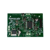
KIT EVALUATION FOR MC33932
Manufacturer
Freescale Semiconductor
Type
MOSFET & Power Driverr
Datasheets
1.KIT33932VWEVBE.pdf
(16 pages)
2.KIT33932VWEVBE.pdf
(21 pages)
3.KIT33932VWEVBE.pdf
(16 pages)
Specifications of KIT33932VWEVBE
Main Purpose
Power Management, Motor Control
Embedded
No
Utilized Ic / Part
MC33932
Primary Attributes
1 H-Bridge Driver
Secondary Attributes
USB, I2C, SPI Interface
Interface Type
USB, SPI
Product
Power Management Modules
Silicon Manufacturer
Freescale
Silicon Core Number
MC33932
Kit Application Type
Power Management
Application Sub Type
Switch
Kit Contents
Evaluation Board, CD, Misc Cables
Rohs Compliant
Yes
Lead Free Status / RoHS Status
Lead free / RoHS Compliant
For Use With/related Products
MC33932


5
EXAMPLE 1. RUNNING THE TEST BOTH H-BRIDGES BATCH FILE
Freescale Semiconductor
10. Next, click on the Data 3 “High” button. The OUT3/4 load or bulb should turn on. The OUT 3/4 LED should be glowing red.
1. Make sure the SPIGen 5.0X program is installed on the PC and it can communicate with the USB/SPI Dongle as
2. Connect the USB/SPI Dongle to the EVB via a 16 pin ribbon cable. Make sure to orient the cable so that pin1 on both the
3. Connect the USB/SPI Dongle to a PC, LED 2 on the USB/SPI Dongle and the VDD LED on the board should both be
4. Attach a +12 VDC supply (do not turn on power yet) to the power connector on the EVB, making sure to observe the GND
5. Attach loads to the OUT1/2 and OUT3/4 terminals . One possible demo load is a 10w halogen G4 Base T3 bulb (used in
6. Launch SPIGen and from the “File” menu, select “Open” and browse to the CD containing the
7. Turn on the +12 Volt Supply. Verify that all is working correctly by clicking on the “Extra Pins” button in the SPIGen main
8. Next, click on the Data 0 “High” button. The OUT1/2 load or bulb should turn on. The OUT 1/2 LED should be glowing
9. Next, click on the Data 2 “High” button. The OUT3/4 load or bulb should turn on. The OUT 3/4 LED should be glowing
1. Click on the “Send a Batch of Commands” Tab in the SPIGen main screen.
2. In the box below the “Commands to Send:” column is a pull-down menu box containing several batch file names. One of
3. Click on this label to load it. You should see a list of commands in the “Command to Send” box.
4. Click on the “Continuous” button and observe that the loads or bulbs you have attached to the EVB board are blinking
To perform the examples included in the CD the following connections and setup must be performed:
There are other demo batch examples that can be run and examined for learning how to use the EVB.
Next, click on the Data 1 “High” button. The OUT1/2 load or bulb should turn on. The OUT 1/2 LED should be glowing red.
Clicking on the DATA 1 “Low” button should turn off the load or bulb and the OUT 1/2 LED.
described in that kit’s documentation.
USB/SPI Dongle and the EVB are connected correctly, pin 1 to pin 1.
illuminated.
and +12V terminals. The current capability of the +12V supply should exceed the maximum total current that the number
of simultaneously ON loads will require.
landscape lighting applications). This load will draw approximately 850 mA and fits nicely into the screw terminals.
“
Generator” to “MC33932 SPI Generator”.
screen and then click on the following buttons to set the up the proper conditions:
green. Clicking on the DATA 0 “Low” button should turn off the load or bulb and the OUT 1/2 LED.
green. Clicking on the DATA 2 “Low” button should turn off the load or bulb and the OUT 3/4 LED.
Clicking on the DATA 3 “Low” button should turn off the load or bulb and the OUT 3/4 LED. If everything described so far
occurs then you are ready to proceed with the remaining examples.
these example batch files is labeled “Test Both H-Bridges”.
twice and then going out in succession.
MC33932_EVB_CONFIGURATION_FILE.spi
Setup and Example Demonstrations
A. Control 0 “Low”
B. Control 1 “High”
C. Control 2 “Low”
D. Control 3 “High”
KIT33932VWEVBE Evaluation Board, Rev. 1.0
” file. The title on the SPIGen screen should change from “Generic SPI
Setup and Example Demonstrations
8
Related parts for KIT33932VWEVBE
Image
Part Number
Description
Manufacturer
Datasheet
Request
R

Part Number:
Description:
Manufacturer:
Freescale Semiconductor, Inc
Datasheet:
Part Number:
Description:
Manufacturer:
Freescale Semiconductor, Inc
Datasheet:
Part Number:
Description:
Manufacturer:
Freescale Semiconductor, Inc
Datasheet:
Part Number:
Description:
Manufacturer:
Freescale Semiconductor, Inc
Datasheet:
Part Number:
Description:
Manufacturer:
Freescale Semiconductor, Inc
Datasheet:
Part Number:
Description:
Manufacturer:
Freescale Semiconductor, Inc
Datasheet:
Part Number:
Description:
Manufacturer:
Freescale Semiconductor, Inc
Datasheet:
Part Number:
Description:
Manufacturer:
Freescale Semiconductor, Inc
Datasheet:
Part Number:
Description:
Manufacturer:
Freescale Semiconductor, Inc
Datasheet:
Part Number:
Description:
Manufacturer:
Freescale Semiconductor, Inc
Datasheet:
Part Number:
Description:
Manufacturer:
Freescale Semiconductor, Inc
Datasheet:
Part Number:
Description:
Manufacturer:
Freescale Semiconductor, Inc
Datasheet:
Part Number:
Description:
Manufacturer:
Freescale Semiconductor, Inc
Datasheet:
Part Number:
Description:
Manufacturer:
Freescale Semiconductor, Inc
Datasheet:
Part Number:
Description:
Manufacturer:
Freescale Semiconductor, Inc
Datasheet: