KIT33932VWEVBE Freescale Semiconductor, KIT33932VWEVBE Datasheet - Page 6
KIT33932VWEVBE
Manufacturer Part Number
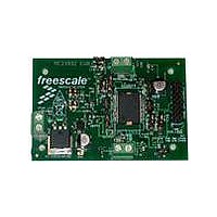
KIT33932VWEVBE
Description
KIT EVALUATION FOR MC33932
Manufacturer
Freescale Semiconductor
Type
MOSFET & Power Driverr
Datasheets
1.KIT33932VWEVBE.pdf
(16 pages)
2.KIT33932VWEVBE.pdf
(21 pages)
3.KIT33932VWEVBE.pdf
(16 pages)
Specifications of KIT33932VWEVBE
Main Purpose
Power Management, Motor Control
Embedded
No
Utilized Ic / Part
MC33932
Primary Attributes
1 H-Bridge Driver
Secondary Attributes
USB, I2C, SPI Interface
Interface Type
USB, SPI
Product
Power Management Modules
Silicon Manufacturer
Freescale
Silicon Core Number
MC33932
Kit Application Type
Power Management
Application Sub Type
Switch
Kit Contents
Evaluation Board, CD, Misc Cables
Rohs Compliant
Yes
Lead Free Status / RoHS Status
Lead free / RoHS Compliant
For Use With/related Products
MC33932


Table 3. Static Electrical Characteristics
values noted reflect the approximate parameter means at T
Specifications given for H-Bridge A apply symmetrically to H-Bridge B.
6
33932
ELECTRICAL CHARACTERISTICS
STATIC ELECTRICAL CHARACTERISTICS
POWER INPUTS (VPWR)
CHARGE PUMP
CONTROL INPUTS
Notes
Operating Voltage Range
Sleep State Supply Current
Standby Supply Current (Part Enabled)
Under-voltage Lockout Thresholds
Charge Pump Voltage (CP Capacitor = 33 nF), No PWM
Charge Pump Voltage (CP Capacitor = 33 nF), PWM = 11 kHz
Operating Input Voltage (IN1, IN2, D1, EN/D2, IN3, IN4, D3, EN/D4)
Input Voltage (IN1, IN2, D1, EN/D2, IN3, IN4, D3, EN/D4)
Logic Input Currents, VPWR = 8.0 V
10.
11.
12.
Characteristics noted under conditions 8.0 V ≤ V
Steady-state
Transient (t < 500 ms)
Quasi-Functional (R
EN/
I
V
V
Hysteresis
V
V
V
V
Logic Threshold HIGH
Logic Threshold LOW
Hysteresis
Input EN/D2, EN/D4 (internal pull-downs), V
Inputs IN1, IN2, D1, IN3, IN4, D3 (internal pull-ups), VIL = 0 V
OUT
PWR(falling)
PWR(rising)
PWR
PWR
PWR
PWR
Device specifications are characterized over the range of 8.0 V ≤ V
reliability. Device is operational down to 5.0V, but below 8.0 V the output resistance may increase by 50 percent.
Device will survive the transient over-voltage indicated for a maximum duration of 500 ms. Transient not to be repeated more than once
every 10 seconds.
I
D2
PWR(SLEEP)
= 0 A, V
= 5.0 V
= 28 V
= 5.0 V
= 28 V
= Logic [0], IN1, IN2, D1 = Logic [1], and I
EN
is with Sleep Mode activated and EN/
= 5.0 V
DS(ON)
(11)
(10)
(12)
Characteristic
May Increase by 50%)
STATIC ELECTRICAL CHARACTERISTICS
IH
= 5.0 V
OUT
PWR
= 0 A
D2
≤ 28 V, - 40°C ≤ T
, = logic [0], and IN1, IN2, D1 = logic [1] or with these inputs left floating.
A
= 25°C under nominal conditions, unless otherwise noted.
V
PWR
I
V
PWR(STANDBY)
UVLO(INACTIVE)
I
V
UVLO(ACTIVE)
V
V
PWR(SLEEP)
V
V
UVLO(HYS)
CP
CP
Symbol
V
PWR(SS)
PWR(QF)
≤ 28 V. Continuous operation above 28 V may degrade device
V
PWR(t)
A
V
V
- V
- V
I
HYS
V
IN
IH
IL
≤ 125°C, GND = 0 V, unless otherwise noted. Typical
I
PWR
PWR
-200
4.15
Min
150
250
8.0
5.0
3.5
3.5
2.0
20
–
–
–
–
–
–
–
–
Analog Integrated Circuit Device Data
Typ
200
400
-80
80
–
–
–
–
–
–
–
–
–
–
–
–
–
–
Freescale Semiconductor
Max
350
200
8.0
5.0
5.5
1.0
-20
28
40
50
20
12
12
–
–
–
–
–
Unit
mA
mV
mV
μA
μA
V
V
V
V
V
V
V
V
Related parts for KIT33932VWEVBE
Image
Part Number
Description
Manufacturer
Datasheet
Request
R

Part Number:
Description:
Manufacturer:
Freescale Semiconductor, Inc
Datasheet:
Part Number:
Description:
Manufacturer:
Freescale Semiconductor, Inc
Datasheet:
Part Number:
Description:
Manufacturer:
Freescale Semiconductor, Inc
Datasheet:
Part Number:
Description:
Manufacturer:
Freescale Semiconductor, Inc
Datasheet:
Part Number:
Description:
Manufacturer:
Freescale Semiconductor, Inc
Datasheet:
Part Number:
Description:
Manufacturer:
Freescale Semiconductor, Inc
Datasheet:
Part Number:
Description:
Manufacturer:
Freescale Semiconductor, Inc
Datasheet:
Part Number:
Description:
Manufacturer:
Freescale Semiconductor, Inc
Datasheet:
Part Number:
Description:
Manufacturer:
Freescale Semiconductor, Inc
Datasheet:
Part Number:
Description:
Manufacturer:
Freescale Semiconductor, Inc
Datasheet:
Part Number:
Description:
Manufacturer:
Freescale Semiconductor, Inc
Datasheet:
Part Number:
Description:
Manufacturer:
Freescale Semiconductor, Inc
Datasheet:
Part Number:
Description:
Manufacturer:
Freescale Semiconductor, Inc
Datasheet:
Part Number:
Description:
Manufacturer:
Freescale Semiconductor, Inc
Datasheet:
Part Number:
Description:
Manufacturer:
Freescale Semiconductor, Inc
Datasheet: