KIT33887EKEVBE Freescale Semiconductor, KIT33887EKEVBE Datasheet - Page 5
KIT33887EKEVBE
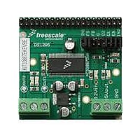
Manufacturer Part Number
KIT33887EKEVBE
Description
BOARD EVALUATION FOR MC33887
Manufacturer
Freescale Semiconductor
Type
Charge Pumpsr
Specifications of KIT33887EKEVBE
Main Purpose
Power Management, H Bridge Driver (Internal FET)
Embedded
No
Utilized Ic / Part
MC33887
Primary Attributes
5A, 5 ~ 28V, PWM to 20kHz, Active Current Limit
Secondary Attributes
Fault Status, Sleep Mode, Proportional Current Mirror Output
Input Voltage
8 V to 20 V
Board Size
50.8 mm x 50.8 mm
Maximum Operating Temperature
+ 85 C
Product
Power Management Modules
Dimensions
50.8 mm x 50.8 mm
Silicon Manufacturer
Freescale
Silicon Core Number
MC33887
Kit Application Type
Power Management - Motor Control
Application Sub Type
DC Brushed Motor
Kit Contents
Board, CD
Rohs Compliant
Yes
Lead Free Status / RoHS Status
Lead free / RoHS Compliant
For Use With/related Products
MC33887


4
Freescale Semiconductor
Using the EVB
Warning: Always wear Safety Glasses when working with electronic modules and/or soldering.
The EVB is provided to quickly evaluate features of the MC33887 device with a simple bench-top setup:
1. Terminal blocks are provided for easy hook-up of power and loads. Strip wire ~ 0.25" before inserting
2. Jumpers are provided at the I/O 2X8 pin header to provide quick set-up of the enable, disables, and
3. To turn on a load in one direction, the inputs should be set as follows: D1 to ground, D2 to +5V, EN to
4. To control the load via PWM, apply a PWM pulse train to either IN1 or IN2, while holding the other
5. A Fault Status indicating LED is included on the board, and can be connected to the Fault Status flag
into terminal block, then tighten down the screw until the wire is snug. Apply a voltage between 5V and
35V to the terminal labeled “12Vin”, and apply the ground return to the terminal labeled “GND”. The
board has a built-in 5V regulator, and up to 500mA may be drawn from the terminal labeled 5Vout, if
desired.
inputs. Alternatively, an uncommitted 2X20 pin header is provided to which the I/O may be wire
wrapped in any desired pinout. This 2X20 pin header will then accept standard 40 pin flat ribbon
cables to provide connection to various Metrowerks Development Systems.
+5V, IN1 to +5V (or left floating, as it has internal pull-ups to +5V), and IN1 to ground. To run current
through the load in the opposite direction, reverse the logic states of IN1 and IN2. (Note: Logic One >
3.3V, Logic Zero <1.4V.)
INput at a steady-state logic level. Swapping the signals applied to IN1 and IN2 will provide control in
the opposite direction.
output by placing a jumper over the two pins opposite the FS label on the 2X8 pin header. By so doing,
the FAULT LED will light whenever the IC encounters any of the following fault conditions: Over
Temperature, Shorted Load, Under Voltage. The LED will remain lit until the IC's fault status flag is
reset by one of the following means: toggling D1, toggling D2, toggling EN, or removing then
reapplying power.
KIT33887EKEVB Evaluation Board,
Rev. 1.0
Using the EVB
5
Related parts for KIT33887EKEVBE
Image
Part Number
Description
Manufacturer
Datasheet
Request
R

Part Number:
Description:
Manufacturer:
Freescale Semiconductor, Inc
Datasheet:
Part Number:
Description:
Manufacturer:
Freescale Semiconductor, Inc
Datasheet:
Part Number:
Description:
Manufacturer:
Freescale Semiconductor, Inc
Datasheet:
Part Number:
Description:
Manufacturer:
Freescale Semiconductor, Inc
Datasheet:
Part Number:
Description:
Manufacturer:
Freescale Semiconductor, Inc
Datasheet:
Part Number:
Description:
Manufacturer:
Freescale Semiconductor, Inc
Datasheet:
Part Number:
Description:
Manufacturer:
Freescale Semiconductor, Inc
Datasheet:
Part Number:
Description:
Manufacturer:
Freescale Semiconductor, Inc
Datasheet:
Part Number:
Description:
Manufacturer:
Freescale Semiconductor, Inc
Datasheet:
Part Number:
Description:
Manufacturer:
Freescale Semiconductor, Inc
Datasheet:
Part Number:
Description:
Manufacturer:
Freescale Semiconductor, Inc
Datasheet:
Part Number:
Description:
Manufacturer:
Freescale Semiconductor, Inc
Datasheet:
Part Number:
Description:
Manufacturer:
Freescale Semiconductor, Inc
Datasheet:
Part Number:
Description:
Manufacturer:
Freescale Semiconductor, Inc
Datasheet:
Part Number:
Description:
Manufacturer:
Freescale Semiconductor, Inc
Datasheet: