BP6A-L Powerex Inc, BP6A-L Datasheet - Page 4
BP6A-L
Manufacturer Part Number
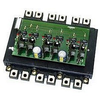
BP6A-L
Description
KIT DEV INTERFACE FOR IPM
Manufacturer
Powerex Inc
Datasheet
1.BP6A-L.pdf
(6 pages)
Specifications of BP6A-L
Main Purpose
Power Management, IGBT Power Module Driver
Embedded
No
Utilized Ic / Part
Powerex Intelligent Power Modules (IPM)
Silicon Manufacturer
Powerex
Application Sub Type
IPM Interface
Kit Application Type
Interface
Silicon Core Number
BP6A
Features
Complete Three-phase Isolated Interface Circuit With Fault Feedback
Kit Contents
PCB And Six VLA106-24151 DC To DC Converters
Rohs Compliant
No
Lead Free Status / RoHS Status
Contains lead / RoHS non-compliant
Secondary Attributes
-
Primary Attributes
-
Lead Free Status / RoHS Status
Contains lead / RoHS non-compliant, Contains lead / RoHS non-compliant


optocoupler’s
optocoupler’s transistor turns on and its collector pulls the
fault feedback line low to indicate a fault. If any of the
IPM’s six fault output signals become active its fault
isolation opto will pull the fault feedback line low. Slow
optos are used because they offer the advantages of
lower cost and higher current transfer ratios. High speed
is not necessary because the IPM disables a faulted
device and produces a fault signal for a minimum of 1ms.
The BP6A also includes an LED in series with each fault
output (D1-D6) to provide a quick visual indication when
the IPM’s fault signal is active. This was included for
trouble shooting purposes only so it can be replaced by a
jumper without affecting the operation of the interface
circuit.
Powerex isolated DC to DC converters (IC13-IC18) as
described above. Each power supply is decoupled at the
IPM’s pins with a low impedance electrolytic capacitor
(C9-C14). These capacitors must be low impedance/high
ripple current types because they are required to supply
the high current gate drive pulses to the IPM’s internal
gate driving circuits.
powered from a single 24VDC supply connected at CN2.
The 24VDC supply is decoupled by the electrolytic
capacitors C7 and C8 to maintain a stable well filtered
source for the DC to DC converters. The current draw on
the 24V supply will range from about 80mA to 380mA
depending on the module being driven and switching
frequency. For a more accurate estimate it is necessary
to use the IPM’s circuit current (I
to obtain the current required by the IPM being used. The
IPM current draw can then be adjusted using the DC to
DC converter efficiency specification to arrive at the
current draw on the 24V supply. Refer to the general IPM
application notes for detailed information.
indicator consisting of an LED (D7) in series with current
limiting resistor (R14) is provided to show that the 24VDC
supply is present.
Designation
R1, R2, R3, R4, R5, R6
R8, R9, R10, R11, R12, R13
R7
R14
C1, C2, C3, C4, C5, C6
C9,C10,C11,C12,C13,C14
C7,C8
D1, D2, D3, D4,D5,D6
D7
IC1, IC2, IC3, IC4, IC5, IC6
IC7, IC8, IC9, IC10, IC11,IC12
CN1
CN3,CN4,CN5
CN2
IC13,IC14,IC15, IC16,IC17,IC18
Isolated control power for the IPM is supplied by
LED
to
The DC to DC converters are
the
Table 2: BP6A Reference Design Component Selection
D
IPM’s
Characteristic
15KΩ, 0.25W
180Ω, 0.25W
4.7KΩ, 0.25W
1.8KΩ, 0.25W
0.1µF, 50V Multi-Layer Ceramic
39µF, 35V, 105C, Low imp.
560µF, 50V, 105C, Low imp.
Super bright red LED
Super bright green LED
Fast Opto coupler HCPL 4504
Slow Opto coupler NEC PS2501
10 pos. 0.1” right angle single row header
Single row bottom entry header receptacle
2 pos. 0.1” right angle single row header
Isolated DC/DC converter
) versus f
fault
C
characteristic
pin.
A power
4
The
VDC
+5
CMOS type
buffer must
sink 15mA
CN1
Figure 4: BP6A External Connections
Description
Input current limiter (15mA@V
High speed opto decoupling capacitor
Control power decoupling capacitor
DC to DC input decoupling capacitor
Control power LED
IPM connector Hirose MDF7-11S-2.54DSA(22)
Powerex P/N VLA106-24151
Control input pull-up
Fault signal pull-up
Power Indicator Current limiter
Fault indicator LED
Control signal isolator
Fault signal isolator
Control signal connector
24VDC Control power connector
To Logic Level Control Circuits
on fault signal
remove noise
RC Filter to
RC~10us
L
=5V)
CN4
CN3
CN5
W
WNF
W
WPF
V
VPF
U
UPF
V
V
V
V
V
V
VNF
V
V
V
V
U
UNF
V
V
V
WN1
WNC
WP1
WPC
VN1
N
VNC
VP1
P
VPC
UP1
P
UPC
UN1
N
UNC
P
N
O
O
O
O
O
O
CN2
VDC
+ -
24
Related parts for BP6A-L
Image
Part Number
Description
Manufacturer
Datasheet
Request
R

Part Number:
Description:
Manufacturer:
Powerex Inc
Datasheet:
Part Number:
Description:
Manufacturer:
Powerex Inc
Datasheet:
Part Number:
Description:
Manufacturer:
Powerex Inc
Datasheet:
Part Number:
Description:
Manufacturer:
Powerex Inc
Datasheet:
Part Number:
Description:
Manufacturer:
Powerex Inc
Datasheet:
Part Number:
Description:
Manufacturer:
Powerex Inc
Datasheet:
Part Number:
Description:
Manufacturer:
Powerex Inc
Datasheet:
Part Number:
Description:
Manufacturer:
Powerex Inc
Datasheet:
Part Number:
Description:
Manufacturer:
Powerex Inc
Datasheet:
Part Number:
Description:
Manufacturer:
Powerex Inc
Datasheet:
Part Number:
Description:
Manufacturer:
Powerex Inc
Datasheet:
Part Number:
Description:
Manufacturer:
Powerex Inc
Datasheet:
Part Number:
Description:
Manufacturer:
Powerex Inc
Datasheet:
Part Number:
Description:
Manufacturer:
Powerex Inc
Datasheet: