CDB3308 Cirrus Logic Inc, CDB3308 Datasheet - Page 4
CDB3308
Manufacturer Part Number
CDB3308
Description
BOARD EVAL FOR CS3308 VOL CTRL
Manufacturer
Cirrus Logic Inc
Specifications of CDB3308
Main Purpose
Audio, Volume Control
Embedded
No
Utilized Ic / Part
CS3308
Primary Attributes
8 Single-Ended Analog Inputs and Outputs, USB or RS232 Interface
Secondary Attributes
Graphic User Interface
Description/function
Audio DSPs
Operating Supply Voltage
5 V
Product
Audio Modules
For Use With/related Products
CS3308
Lead Free Status / RoHS Status
Contains lead / RoHS non-compliant
Lead Free Status / RoHS Status
Lead free / RoHS Compliant, Contains lead / RoHS non-compliant
Other names
598-1496


4
1.5
1.6
1.7
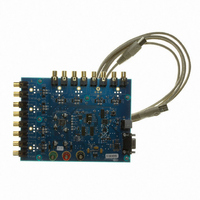
The 10-pin, 2 column header, J88, provides unidirectional output access to the CS3308’s SPI MOSI and
CCLK signals, as well as its AD0, ENOut, and MUTE signals. All of the signals re-driven versions of those
present directly on their respective I/O pins on the CS3308. This header may be used to connect the serial
control signals between 2 or more CDB3308’s (out of J88 on one and in to J17 on another) for multiple
CS3308 SPI serial control evaluation.
RCA connectors supply the CS3308 analog inputs through single-ended passive circuits with no input filter-
ing. Refer to the CS3308 data sheet for the maximum input signal level.
Each analog input may be AC or DC coupled to its respective RCA connector. This selection is made via
the 2-pin headers labeled “DC Couple Input” and placed adjacent to each input connector on the board. To
DC couple an input connector, place a shunt across the respective header. To AC couple an input connec-
tor, remove the shunt from the respective header. By default, the input connectors are AC coupled to the
CS3308’s inputs.
The CS3308 analog outputs are routed through single-ended passive circuits with no output filtering and
connected to RCA jacks for easy evaluation.
Each analog output may be AC or DC coupled to its respective RCA connector. This selection is made via
the 2-pin headers labeled “DC Couple Output” and placed adjacent to each output connector on the board.
To DC couple an output connector, place a shunt across the respective header. To AC couple an output
connector, remove the shunt from the respective header. By default, the output connectors are AC coupled
to the CS3308’s outputs.
USB and RS-232 connections are provided to facilitate software control of the CS3308’s internal registers.
A graphical user interface is available for the CDB3308 to allow easy manipulation of the CS3308’s internal
registers. See the CS3308 datasheet for complete internal register descriptions.
To enable the CDB3308, simply connect the supplied USB cable from an available USB port on a PC to the
USB connector (J37), or alternatively connect a 9-pin serial cable from an available COM port on a PC to
the RS-232 connector (J42) and launch the Cirrus Logic FlexGUI software.
Refer to
Analog Inputs
Analog Outputs
PC Interfaces
“PC Software Control” on page 5
for a description of the Graphical User Interface (GUI).
CDB3308
DS702DB2
Related parts for CDB3308
Image
Part Number
Description
Manufacturer
Datasheet
Request
R

Part Number:
Description:
Development Kit
Manufacturer:
Cirrus Logic Inc
Datasheet:
Part Number:
Description:
Development Kit
Manufacturer:
Cirrus Logic Inc
Datasheet:


Part Number:
Description:
High-efficiency PFC + Fluorescent Lamp Driver Reference Design
Manufacturer:
Cirrus Logic Inc
Datasheet:
Part Number:
Description:
Development Kit
Manufacturer:
Cirrus Logic Inc
Datasheet:
Part Number:
Description:
Development Kit
Manufacturer:
Cirrus Logic Inc
Datasheet:

Part Number:
Description:
Development Kit
Manufacturer:
Cirrus Logic Inc
Datasheet:
Part Number:
Description:
Development Kit
Manufacturer:
Cirrus Logic Inc
Datasheet:
Part Number:
Description:
Development Kit
Manufacturer:
Cirrus Logic Inc
Datasheet:
Part Number:
Description:
Development Kit
Manufacturer:
Cirrus Logic Inc
Datasheet:

Part Number:
Description:
EVALUATION BOARD FOR CS8427
Manufacturer:
Cirrus Logic Inc
Datasheet:

Part Number:
Description:
BOARD EVAL FOR CS8416 RCVR
Manufacturer:
Cirrus Logic Inc
Datasheet:

Part Number:
Description:
EVALUATION BOARD FOR CS8420
Manufacturer:
Cirrus Logic Inc
Datasheet:

Part Number:
Description:
KIT DEVELOPMENT EP9315 ARM9
Manufacturer:
Cirrus Logic Inc
Datasheet:

Part Number:
Description:
KIT DEVELOPMENT EP9302 ARM9
Manufacturer:
Cirrus Logic Inc
Datasheet: