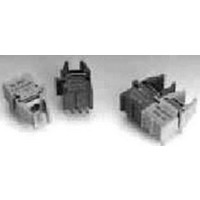
HFBR-0536 Avago Technologies US Inc., HFBR-0536 Datasheet - Page 3

HFBR-0536
Manufacturer Part Number
HFBR-0536
Description
KIT EVAL FIBER OPTIC 32MBD
Manufacturer
Avago Technologies US Inc.
Specifications of HFBR-0536
Main Purpose
Interface, Fiber Optics
Embedded
No
Utilized Ic / Part
HFBR-1527, HFBR-2526
Primary Attributes
DC ~ 32MBd TTL
Secondary Attributes
TTL-Compatible
Tool / Board Applications
Fiber Optic Transceivers
Mcu Supported Families
HFBR-1527
Development Tool Type
Hardware / Software - Eval/Demo Board
Lead Free Status / RoHS Status
Contains lead / RoHS non-compliant
Lead Free Status / RoHS Status
Lead free / RoHS Compliant, Contains lead / RoHS non-compliant
Other names
516-2145
HFBR-0536
HFBR-0536
Plastic Optical Fiber (1 mm POF) Transmitter Application Circuit:
Performance of the HFBR-15X7 transmitter in the recommended application circuit (Figure 1) for POF; 1-
125 MBd, 25°C.
Hard Clad Silica Fiber (200
the HFBR-15X7 transmitter in the recommended application circuit (Figure 1) for HCS; 1-125 MBd, 25°C.
Notes:
1. Average optical power is measured with an average power meter at 50% duty cycle, after 1 meter of fiber.
2. To allow the LED to switch at high speeds, the recommended drive circuit modulates LED light output between two non-zero power
3. High and low level LED currents refer to the current through the HFBR-15X7 LED. The low level LED “off” current, sometimes
Average Optical Power 1 mm POF
Average Modulated Power 1 mm POF
Optical Rise Time (10% to 90%)
Optical Fall Time (90% to 10%)
High Level LED Current (On)
Low Level LED Current (Off)
Optical Overshoot - 1 mm POF
Transmitter Application Circuit
Current Consumption - 1 mm POF
Average Optical Power 200 µm HCS
Average Modulated Power 200 µm HCS
Optical Rise Time (10% to 90%)
Optical Fall Time (90% to 10%)
High Level LED Current (On)
Low Level LED Current (Off)
Optical Overshoot - 200 µm HCS
Transmitter Application Circuit
Current Consumption - 200 µm HCS
levels. The modulated (useful) power is the difference between the high and low level of light output power (transmitted) or input
power (received), which can be measured with an average power meter as a function of duty cycle (see Figure 3). Average Modulated
Power is defined as one half the slope of the average power versus duty cycle:
referred to as “hold-on” current, is prebias supplied to the LED during the off state to facilitate fast switching speeds.
Parameter
Parameter
Average Modulated Power = ––——————————————————————
µ
m HCS) Transmitter Application Circuit:
Symbol
P
Symbol
P
I
I
I
mod
F,H
F,L
t
t
CC
avg
[P
r
P
f
P
I
I
I
mod
F,H
F,L
t
t
CC
avg
avg
r
f
@ 80% duty cycle - P
Typical
-11.3
-9.7
110
Typical
2.1
2.8
19
45
3
-14.6
-16.2
130
3.1
3.4
(2) [0.80 - 0.20]
60
30
6
Unit
dBm
dBm
avg
mA
mA
mA
ns
ns
%
Unit
dBm
dBm
mA
mA
mA
ns
ns
%
@ 20% duty cycle]
Condition
50% Duty
Condition
50% Duty
5 MHz
5 MHz
Cycle
5 MHz
5 MHz
Cycle
Performance of
Note 1, Fig 3
Note 2, Fig 3
Note 1, Fig 3
Note 2, Fig 3
Figure 1
Figure 1
Note 3
Note 3
Note 3
Note 3
Note
Note


