ATA6826-DK Atmel, ATA6826-DK Datasheet - Page 13
ATA6826-DK
Manufacturer Part Number
ATA6826-DK
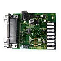
Description
BOARD EVALUATION FOR ATA6826
Manufacturer
Atmel
Specifications of ATA6826-DK
Main Purpose
Power Management, Half H-Bridge Driver (Internal FET)
Embedded
No
Utilized Ic / Part
ATA6826
Primary Attributes
3 Half H-Bridge Drivers, 1A, 2 kV ESD Protection
Secondary Attributes
Short-Circuit, Thermal & Undervoltage Protection
Lead Free Status / RoHS Status
Contains lead / RoHS non-compliant


5. Thermal Considerations
5.1
4981A–AUTO–02/07
Cooling Area Design
The IC should be connected to a cooling area onboard. All thermal pins (4 GND pins) are
directly connected to the cooling area.
housing of the ATA6826. The cooling area extension should be increased or decreased accord-
ing to the required power dissipation (see
as follows: 2 × L² = cooling area extension [mm²].
The effect of the cooling area on the PCB can be further improved if the bottom side of the PCB
is ground-plated and thermal vias are placed along the cooling area. A via diameter of 0.3 mm to
0.4 mm and a spacing of 1 mm to 1.5 mm has proven to be most suitable. Some care should be
taken of the copper area's planarity; it should especially be avoided that any solder bumps arise
at the thermal vias.
Figure 5-1.
Figure 5-2.
Recommended Cooling Area Extension
Thermal Resistance Versus Adapted Cooling-area Size on Board
40.0
30.0
70.0
65.0
60.0
50.0
45.0
35.0
25.0
20.0
55.0
0.0
5.0
10.0
Figure 5-1
Figure
15.0
L (mm)
shows the cooling arrangement with the SO14
5-2). The cooling area extension is calculated
20.0
25.0
30.0
L
35.0
40.0
ATA6826
13
Related parts for ATA6826-DK
Image
Part Number
Description
Manufacturer
Datasheet
Request
R

Part Number:
Description:
Triple Half-bridge DMOS Output Driver with Serial Input Control
Manufacturer:
ATMEL Corporation
Datasheet:

Part Number:
Description:
MOSFET & Power Driver ICs Triple Half-Bridge Driver
Manufacturer:
Atmel
Datasheet:
Part Number:
Description:
MOSFET & Power Driver ICs Triple Half-Bridge Driver
Manufacturer:
Atmel
Datasheet:

Part Number:
Description:
DEV KIT FOR AVR/AVR32
Manufacturer:
Atmel
Datasheet:
Part Number:
Description:
INTERVAL AND WIPE/WASH WIPER CONTROL IC WITH DELAY
Manufacturer:
ATMEL Corporation
Datasheet:
Part Number:
Description:
Low-Voltage Voice-Switched IC for Hands-Free Operation
Manufacturer:
ATMEL Corporation
Datasheet:
Part Number:
Description:
MONOLITHIC INTEGRATED FEATUREPHONE CIRCUIT
Manufacturer:
ATMEL Corporation
Datasheet:
Part Number:
Description:
AM-FM Receiver IC U4255BM-M
Manufacturer:
ATMEL Corporation
Datasheet:
Part Number:
Description:
Monolithic Integrated Feature Phone Circuit
Manufacturer:
ATMEL Corporation
Datasheet:
Part Number:
Description:
Multistandard Video-IF and Quasi Parallel Sound Processing
Manufacturer:
ATMEL Corporation
Datasheet:
Part Number:
Description:
High-performance EE PLD
Manufacturer:
ATMEL Corporation
Datasheet:
Part Number:
Description:
8-bit Flash Microcontroller
Manufacturer:
ATMEL Corporation
Datasheet: