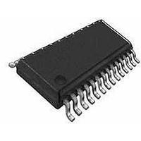
PS5163EV Microchip Technology, PS5163EV Datasheet - Page 2

PS5163EV
Manufacturer Part Number
PS5163EV
Description
KIT EVALUATION PS5163 W/PS051
Manufacturer
Microchip Technology
Series
PowerSmart®r
Specifications of PS5163EV
Main Purpose
Power Management, Battery Pack Monitor
Utilized Ic / Part
PS5163
Operating Supply Voltage
11.1 V to 25.0 V
Package / Case
SSOP-28
Mounting Style
SMD/SMT
Lead Free Status / RoHS Status
Lead free / RoHS Compliant
Secondary Attributes
-
Embedded
-
Primary Attributes
-
Lead Free Status / Rohs Status
Lead free / RoHS Compliant
PS5163
1.0
The PS5163 module is a complete smart battery
controller subsystem based on the Microchip PS501
field reprogrammable battery manager with patented
Accuron
operate in a battery pack consisting of three (3) series
connected Li-based cells. The module consists of the
Microchip PS501 battery manager IC with a four-LED
SOC display and an optional connection for an external
thermistor.
1.1
Follow these directions to assemble a pack with the
PS5163 module.
• Use standard precautions when handling static
• Modules should be connected to battery cells in
• The connection sequence is critical to successful
FIGURE 1-1:
DS21851B-page 2
sensitive devices.
the order indicated below to insure proper start-up
and operation. Wires should be attached to the
modules first and then connected to the battery
cells as instructed.
use of the PS501 family of CMOS ASICs. The
pack positive should be securely connected to the
module first, followed by the intermediate cells
from most positive to least positive and finally,
pack negative.
®
GENERAL DESCRIPTION
Quick Start – Pack Assembly
technology. The module is designed to
CONNECTION POINTS (SIDE 1)
Step 1)
Step 2)
Step 3)
Step 4)
Step 5)
Step 6)
Step 7)
Step 8)
Configure the module for optional external
thermistor
shipped configured to use the internal tem-
perature sensor only. To add an external
thermistor to the board, remove resistor R16
(side 2) and connect the thermistor across
via TN and TR.
Connect wires to module. Use large diameter
wire (18 AWG-20 AWG) for current carrying
lines from VR, V1, B+ and BN. All others are
signal only lines (24 to 22 AWG).
Connect external connector to BN, T, C, D
and B+.
Connect V1 to the most positive point on the
battery cell stack.
Connect the negative end of the top-most
cell to V2 and the negative end of the second
cell to V3.
Connect VR to the most negative point on the
battery cell stack.
Program
Microchip’s software and PowerCal™ board
or PowerInfo™ board hardware.
The memory parameters can be changed at
will using the utilities on the memory page in
the software.
Calibrate the pack using the software and
PowerCal™ board hardware. The pack is
now ready for use.
the
use.
2004 Microchip Technology Inc.
assembled
PS5163
modules
pack
using
are


