DC1568A Linear Technology, DC1568A Datasheet - Page 2
DC1568A
Manufacturer Part Number
DC1568A
Description
BOARD BATTERY CHARGER SOLAR PWR
Manufacturer
Linear Technology
Datasheet
1.DC1568A.pdf
(6 pages)
Specifications of DC1568A
Main Purpose
Power Management, Battery Charger
Embedded
No
Utilized Ic / Part
LT3652
Primary Attributes
Multi-Chemistry, Solar Power
Secondary Attributes
LED Status Indicators
Silicon Manufacturer
Linear Technology
Silicon Core Number
LTC3652
Kit Application Type
Power Management - Battery
Application Sub Type
Battery Charger
Development Tool Type
Hardware - Eval/Demo Board
Lead Free Status / RoHS Status
Lead free / RoHS Compliant


LT3652EDD
rent is set using an external inductor current sense resis-
tor. A maximum charge current programming pin allows
dynamic manipulation of the battery charge current. The
LT3650 also incorporates a system input-supply current
limit control feature that servos the battery charge cur-
rent to accommodate overall system load requirements.
The LT3652 automatically enters a battery precondition
mode if the sensed battery voltage is very low. In this
mode, the charging current is reduced to 15% of the
programmed maximum, as set by the inductor sense
resistor, R
internally set threshold of 5.7V / cell, the IC automatically
increases maximum charging current to the full pro-
grammed value.
The LT3652 can use a charge-current based ‘C/10’ ter-
mination scheme, which ends a charge cycle when the
battery charge current falls to 1/10
maximum charge current. The LT3652 also contains an
internal charge cycle control timer, for timer-based ter-
mination. When using the internal timer, the IC com-
bines C/10 detection with a programmable time con-
straint, during which the charging cycle can continue
beyond the C/10 level to “top-off” a battery. The charge
cycle terminates when a specific time elapses, typically 3
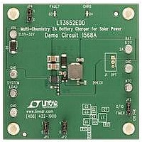
QUICK START PROCEDURE
Demonstration circuit 1568A is easy to set up to evaluate
the performance of the LT3652EDD.
Using short twisted pair leads for any power connec-
tions, with all loads and power supplies off, refer to
Figure 1 for the proper measurement and equipment
setup.
Follow the procedure below:
1. Jumper and Power Supply Setting:
2
JP1 = 1
JP2 = 1
JP3 = C/10
SENSE
. Once the battery voltage climbs above an
JP4 = 1
PS1 = OFF
PS2 = OFF
th
the programmed
hours. When the timer-based scheme is used, the IC
also supports ‘bad-battery’ detection, which triggers a
system fault if a battery stays in precondition mode for
more than 1/8
Once charging is terminated and the LT3652 is not ac-
tively charging, the IC automatically enters a low-current
standby mode where supply bias currents are reduced to
< 100uA. If the battery voltage drops 2.5% from the full-
charge float voltage, the LT3652 engages an automatic
charge cycle restart. The IC also automatically restarts a
new charge cycle after a bad battery fault once the failed
battery is removed and replaced with another battery.
The LT3652 includes provisions for a battery tempera-
ture monitoring circuit. This feature monitors battery
temperature during the charging cycle using a thermis-
tor, and suspends charging and signals a fault condition
if the battery temperature moves outside a safe charging
range of 0
The LT3652 contains two digital open-collector outputs,
which provide charger status and signal fault conditions.
These binary-coded pins signal battery charging, standby
or shutdown modes, battery temperature faults, and bad
battery faults.
2. Turn on PS2 and slowly increase the voltage to
3. Verify that the battery charging current, IBAT, is
4. Increase PS2 until VBAT is 7.2V. Verify the input
5.4V while monitoring the current into the BAT
pin. If the current is less than 5mA, turn on PS1.
Increase the voltage on PS1 to 5V while monitor-
ing the input current. If the current is less than
5mA, increase PS1 to 12V.
between 250mA and 350mA. The CHRG LED
should be on and the FAULT LED should be off.
current, IIN, is between 1.3A and 1.7A, the battery
current, IBAT, is between 1.775A and 2.225A and
that the CHRG LED is on.
O
C to 50
th
of the total charge cycle time.
O
C.
Related parts for DC1568A
Image
Part Number
Description
Manufacturer
Datasheet
Request
R

Part Number:
Description:
KIT DEV SP ADPT NO RAVEN
Manufacturer:
Digi International
Datasheet:

Part Number:
Description:
VIDEO DAUGHTER CARD
Manufacturer:
Altera
Datasheet:

Part Number:
Description:
KIT DEV SP ADAPTER
Manufacturer:
Digi International
Datasheet:

Part Number:
Description:
BOARD EVALUATION
Manufacturer:
STMicroelectronics
Datasheet:

Part Number:
Description:
CD ROM LINEARVIEW DATASHEETS
Manufacturer:
Linear Technology

Part Number:
Description:
Standalone Linear Li-Ion Battery Charger with Thermal Regulation in ThinSOT
Manufacturer:
Linear Technology Corporation
Datasheet:
Part Number:
Description:
Low noise, high frequency, 8th order linear phase lowpass filter
Manufacturer:
Linear Technology Corporation
Datasheet:
Part Number:
Description:
Manufacturer:
Linear Technology Corporation
Datasheet:
Part Number:
Description:
Manufacturer:
Linear Technology Corporation
Datasheet:
Part Number:
Description:
Manufacturer:
Linear Technology Corporation
Datasheet:
Part Number:
Description:
Manufacturer:
Linear Technology Corporation
Datasheet:
Part Number:
Description:
Manufacturer:
Linear Technology Corporation
Datasheet:
Part Number:
Description:
Manufacturer:
Linear Technology Corporation
Datasheet:
Part Number:
Description:
Manufacturer:
Linear Technology Corporation
Datasheet: