GPIODM-KPLCD Microchip Technology, GPIODM-KPLCD Datasheet - Page 14
GPIODM-KPLCD
Manufacturer Part Number
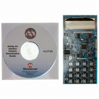
GPIODM-KPLCD
Description
BOARD DEMO LCD GPIO EXP KEYPAD
Manufacturer
Microchip Technology
Datasheet
1.GPIODM-KPLCD.pdf
(28 pages)
Specifications of GPIODM-KPLCD
Main Purpose
Interface, Front Panel Controller, LCD
Embedded
Yes, MCU, 8-Bit
Utilized Ic / Part
MCP23008, MCP23S08, MCP23017, MCP23S17, PIC18F4550, MCP1702
Primary Attributes
(2) 8-Bit and (2) 16-Bit GPIO Expanders, 4x4 Keypad, 2x16 LCD
Secondary Attributes
Headers for the MCP23x08 and MCP23x17
Silicon Manufacturer
Microchip
Core Architecture
PIC
Core Sub-architecture
PIC18
Features
SPI And I2C Buses, Keypad And LCD Interface, ICSP Header
Kit Contents
Board
Silicon Core Number
PIC18F
Silicon Family Name
PIC18F4xxx
Rohs Compliant
Yes
Lead Free Status / RoHS Status
Not applicable / Not applicable
For Use With
MCP23S08/17, MCP23008/17
Lead Free Status / RoHS Status
Lead free / RoHS Compliant, Not applicable / Not applicable


GPIO Expander Keypad and LCD Demo Board User’s Guide
2.5
DS51636A-page 10
FIRMWARE DESCRIPTION
See
Main Function:
1. The firmware first configures the PIC MCU.
2. The MCP23X08 and MCP23X17 devices are configured. I
3. The LCD splash screen is shown.
4. Wait for an interrupt from the MCP23X08. An interrupt will occur when a button
5. After the interrupt occurs, the firmware calls the Scan_Buttons routine.
6. Then the Update_LCD routine.
Scan_Buttons Function:
1. Read INTCAP register. This register contains a snapshot of the port condition
2. Swap inputs and outputs so the rows can be read.
3. Read GPIO register and merge with variable containing INTCAP value.
4. The pressed key is determined by looking up the result in a lookup table.
Update_LCD Function:
1. The LCD is updated based on which button was pressed.
selected first by default. The SPI devices I/O are held in reset.
is pressed. Four (4) inputs are configured to interrupt on falling edge. These
inputs are for the “columns” of the keypad matrix.
when the interrupt occurred.
Figure 2-3
for the main firmware flow diagram.
© 2006 Microchip Technology Inc.
2
C Devices are
Related parts for GPIODM-KPLCD
Image
Part Number
Description
Manufacturer
Datasheet
Request
R

Part Number:
Description:
Manufacturer:
Microchip Technology Inc.
Datasheet:
Part Number:
Description:
Manufacturer:
Microchip Technology Inc.
Datasheet:
Part Number:
Description:
Manufacturer:
Microchip Technology Inc.
Datasheet:
Part Number:
Description:
Manufacturer:
Microchip Technology Inc.
Datasheet:
Part Number:
Description:
Manufacturer:
Microchip Technology Inc.
Datasheet:
Part Number:
Description:
Manufacturer:
Microchip Technology Inc.
Datasheet:
Part Number:
Description:
Manufacturer:
Microchip Technology Inc.
Datasheet:
Part Number:
Description:
Manufacturer:
Microchip Technology Inc.
Datasheet: