MCP73831EV Microchip Technology, MCP73831EV Datasheet - Page 14
MCP73831EV
Manufacturer Part Number
MCP73831EV
Description
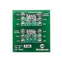
BOARD DEMO FOR MCP73831
Manufacturer
Microchip Technology
Type
Battery Managementr
Specifications of MCP73831EV
Main Purpose
Power Management, Battery Charger
Utilized Ic / Part
MCP73831
Product
Power Management Modules
Kit Contents
2x MCP73831 Evaluation Boards, Users Guide, Data Sheet
Features
Automatic Charge Termination, Charge Current Monitor, Preconditioning Of Deeply Depleted Cells
Svhc
No SVHC (15-Dec-2010)
Rohs Compliant
Yes
For Use With/related Products
MCP73831
Lead Free Status / RoHS Status
Contains lead / RoHS non-compliant
Secondary Attributes
-
Embedded
-
Primary Attributes
-
Lead Free Status / Rohs Status
Lead free / RoHS Compliant


MCP73831/2
4.5
When the voltage at the V
tion voltage, V
The regulation voltage is factory set to 4.2V, 4.35V,
4.40V, or 4.50V with a tolerance of ±0.75%.
4.6
The charge cycle is terminated when, during Constant-
Voltage mode, the average charge current diminishes
below a percentage of the programmed charge current
(established with the value of the resistor connected to
the PROG pin). A 1 ms filter time on the termination
comparator ensures that transient load conditions do
not result in premature charge cycle termination. The
percentage or ratio of the current is factory set. Refer to
Section 1.0 “Electrical Characteristics” for charge
termination
Identification System” for standard options.
The charge current is latched off and the MCP73831/2
enter a Charge Complete mode.
4.7
The MCP73831/2 continuously monitor the voltage at
the V
voltage drops below the recharge threshold, another
charge cycle begins and current is once again supplied
to the battery or load. The recharge threshold is factory
set. Refer to Section 1.0 “Electrical Characteristics”
for recharge threshold options and the ”Product
Identification System” for standard options.
DS21984E-page 14
BAT
Constant-Voltage Mode
Charge Termination
Automatic Recharge
pin in the Charge Complete mode. If the
current
REG
, constant voltage regulation begins.
options
BAT
pin reaches the regula-
and
the
”Product
4.8
The MCP73831/2 limit the charge current based on the
die temperature. The thermal regulation optimizes the
charge cycle time while maintaining device reliability.
Figure 4-2
MCP73831/2.
FIGURE 4-2:
4.9
The MCP73831/2 suspend charge if the die tempera-
ture exceeds 150°C. Charging will resume when the
die temperature has cooled by approximately 10°C.
525
450
375
300
225
150
75
Thermal Regulation
Thermal Shutdown
0
depicts the thermal regulation for the
Junction Temperature (°C)
Thermal Regulation.
© 2008 Microchip Technology Inc.
R
PROG
= 2 kΩ
Related parts for MCP73831EV
Image
Part Number
Description
Manufacturer
Datasheet
Request
R

Part Number:
Description:
Manufacturer:
Microchip Technology Inc.
Datasheet:
Part Number:
Description:
Manufacturer:
Microchip Technology Inc.
Datasheet:
Part Number:
Description:
Manufacturer:
Microchip Technology Inc.
Datasheet:
Part Number:
Description:
Manufacturer:
Microchip Technology Inc.
Datasheet:
Part Number:
Description:
Manufacturer:
Microchip Technology Inc.
Datasheet:
Part Number:
Description:
Manufacturer:
Microchip Technology Inc.
Datasheet:
Part Number:
Description:
Manufacturer:
Microchip Technology Inc.
Datasheet:
Part Number:
Description:
Manufacturer:
Microchip Technology Inc.
Datasheet: