MCP3905RD-PM1 Microchip Technology, MCP3905RD-PM1 Datasheet - Page 19
MCP3905RD-PM1
Manufacturer Part Number
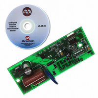
MCP3905RD-PM1
Description
REFERENCE DESIGN FOR MCP3905
Manufacturer
Microchip Technology
Specifications of MCP3905RD-PM1
Main Purpose
Power Management, Energy/Power Meter
Embedded
No
Utilized Ic / Part
MCP3905/6
Primary Attributes
1-Phase, 220 VAC, In Case, With Mechanical Counter
Secondary Attributes
On Board Transformerless AC/DC 5V Supply
Silicon Manufacturer
Microchip
Silicon Core Number
MCP3905A,MCP3906A
Kit Application Type
Power Management
Application Sub Type
Energy Meter
Kit Contents
Design Guides
Lead Free Status / RoHS Status
Lead free / RoHS Compliant
Available stocks
Company
Part Number
Manufacturer
Quantity
Price
Company:

Part Number:
MCP3905RD-PM1
Manufacturer:
MICROCHIP
Quantity:
12 000


4.7
The thresholds for the accumulated energy are
different for F
ent transfer functions). The F
frequencies are quite low in order to allow superior
integration time (see Section 4.6 “Low-Pass Filter
and DTF Converter”). The F
can be calculated with the following equation:
EQUATION 4-1:
TABLE 4-3:
© 2009 Microchip Technology Inc.
Where:
V
REF
F1
0
0
1
1
F
V
V
G = the PGA gain on Channel 0
C
0
1
F
= the RMS differential voltage on Channel 0
= the RMS differential voltage on Channel 1
= the frequency constant selected
= the voltage reference
F
Frequencies
OUT
OUT0/1
(current channel)
OUT0/1
(
F0
Hz
0
1
0
1
)
OUTPUT FREQUENCY CONSTANT FC FOR FOUT0/1 (V
and HF
=
and HF
F
OUTPUT EQUATION
8.06
---------------------------------------------------------- -
OUT
MCLK/2
MCLK/2
MCLK/2
MCLK/2
F
×
C
OUT
OUT
FREQUENCY
V
(
OUT0/1
(Hz)
0
V
OUT0/1
×
REF
(i.e., they have differ-
21
20
19
18
V
Output
1
)
×
2
output frequency
G F
allowed output
×
(MCLK = 3.58 MHz)
C
F
13.66
C
1.71
3.41
6.83
(Hz)
For a given DC input V, the DC and RMS values are
equivalent. For a given AC input signal with peak-to-
peak amplitude of V, the equivalent RMS value is V/
sqrt(2), assuming purely sinusoidal signals. Note that
since the active (real) power is the product of two RMS
inputs, the output frequencies of an AC signal is half
that of the DC equivalent signal, again assuming purely
sinusoidal AC signals. The constant F
F
F
settings.
OUT0
OUT0/1
F
OUT
with Full-Scale
and F
output frequencies for the different logic
Frequency (Hz)
DC Inputs
0.74
1.48
2.96
5.93
OUT1
digital settings.
REF
MCP3905/06
= 2.4V)
F
OUT
with Full-Scale
Frequency (Hz)
AC Inputs
DS21948E-page 19
C
Table 4-3
depends on the
0.37
0.74
1.48
2.96
shows
Related parts for MCP3905RD-PM1
Image
Part Number
Description
Manufacturer
Datasheet
Request
R

Part Number:
Description:
IC ENERGY METER 24-SSOP
Manufacturer:
Microchip Technology
Datasheet:

Part Number:
Description:
Energy-Metering ICs with Active (Real) Power Pulse Output
Manufacturer:
Microchip Technology
Part Number:
Description:
(MCP3905 / MCP3906) Energy-Metering ICs
Manufacturer:
Microchip Technology
Datasheet:

Part Number:
Description:
Manufacturer:
Microchip Technology Inc.
Datasheet:
Part Number:
Description:
Manufacturer:
Microchip Technology Inc.
Datasheet:
Part Number:
Description:
Manufacturer:
Microchip Technology Inc.
Datasheet:
Part Number:
Description:
Manufacturer:
Microchip Technology Inc.
Datasheet:
Part Number:
Description:
Manufacturer:
Microchip Technology Inc.
Datasheet:
Part Number:
Description:
Manufacturer:
Microchip Technology Inc.
Datasheet:
Part Number:
Description:
Manufacturer:
Microchip Technology Inc.
Datasheet: