MCP7382XEV Microchip Technology, MCP7382XEV Datasheet - Page 13
MCP7382XEV
Manufacturer Part Number
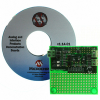
MCP7382XEV
Description
KIT EVALUATION FOR MCP7382X
Manufacturer
Microchip Technology
Type
Battery Managementr
Datasheet
1.MCP7382XEV.pdf
(22 pages)
Specifications of MCP7382XEV
Main Purpose
Power Management, Battery Charger
Embedded
No
Utilized Ic / Part
MCP73826, MCP73827, MCP73828
Primary Attributes
1 Cell- Li-Ion / Li-Pol, 4.2V @ 1A, 4.5 ~ 6 Vin
Product
Power Management Modules
For Use With/related Products
MCP73826, MCP73827, MCP73828
Lead Free Status / RoHS Status
Lead free / RoHS Compliant
Secondary Attributes
-
Lead Free Status / Rohs Status
Lead free / RoHS Compliant
Other names
MCP7382XEVR
MCP7382XEVR
MCP7382XEVR


2.4
© 2006 Microchip Technology Inc.
DETAILED DESCRIPTION
The MCP7382X Evaluation Board is set-up to evaluate simple, stand-alone, linear
charging of single cell Li-Ion battery packs. Each of the three Li-Ion battery chargers
can be evaluated independently. The chargers provide controlled current charging fol-
lowed by constant voltage charging. The MCP73826, U1, is provided in a 6-pin SOT23
package and is equipped with shutdown control. The MCP73827, U2, is provided in an
8-pin MSOP package. In addition to shutdown control, the MCP73827 signals when the
charge cycle transitions from controlled current mode to constant voltage mode. An
LED, D3, is illuminated during the controlled current mode. A voltage representation of
the charge current, I
profile. The MCP73828, U3, is also provided in an 8-pin MSOP package. In addition to
shutdown control, the MCP73828 signals when the charge current has diminished
below ten percent of the peak charge current. An LED, D2, is illuminated indicating full
charge. A thermistor input is provided to inhibit charging when the cell temperature is
outside a pre-defined window. Refer to the appropriate data sheets for details on the
individual device features.
2.4.1
The MCP7382X Evaluation Board is designed to provide an output current of 1A, typi-
cal. A 5V ±10%, 6W input source should be utilized to power the evaluation kit. JP1
terminal 1 is the positive input source connection. JP1 terminal 2 is the negative input
source connection.
Higher or lower output currents can be obtained by adjusting the value of the sense
resistor, R1. A corresponding higher or lower power input source may need to be uti-
lized. Care should be taken not to over stress the pass transistor, Q1, with excessive
power dissipation when higher output currents are desired.
2.4.2
The MCP7382X Evaluation Board is designed to provide reverse blocking protection in
the event a reversed polarity input source is connected to JP1. The reverse blocking
protection diode, D1, also ensures that a faulted or shorted input source will not
adversely effect the battery pack.
2.4.3
Two headers, JP2 and JP3 are used to connect to an external Li-Ion battery pack and
optional protection thermistor. JP2 terminal 1 is the battery pack positive connection,
JP2 terminal 2 is the negative battery pack connection. JP3 terminal 1 is for connection
to a 10 k ohm NTC thermistor situated in the battery pack for temperature sensing. JP3
terminal 2 is the negative reference for the thermistor.
Note:
Input Source
Reverse Blocking Protection
Battery Headers
Improper connection of the battery may result in damage to the
battery and the possibility of personal injury. It is also important to
avoid shorting the battery terminals together.
MON
, is provided for a host microcontroller to monitor the charge
DS51267B-page 9
Related parts for MCP7382XEV
Image
Part Number
Description
Manufacturer
Datasheet
Request
R

Part Number:
Description:
Manufacturer:
Microchip Technology Inc.
Datasheet:
Part Number:
Description:
Manufacturer:
Microchip Technology Inc.
Datasheet:
Part Number:
Description:
Manufacturer:
Microchip Technology Inc.
Datasheet:
Part Number:
Description:
Manufacturer:
Microchip Technology Inc.
Datasheet:
Part Number:
Description:
Manufacturer:
Microchip Technology Inc.
Datasheet:
Part Number:
Description:
Manufacturer:
Microchip Technology Inc.
Datasheet:
Part Number:
Description:
Manufacturer:
Microchip Technology Inc.
Datasheet:
Part Number:
Description:
Manufacturer:
Microchip Technology Inc.
Datasheet: